

Supplementary metrology position coordinates determination system including an alignment sensor for use with a robot
- Summary
- Abstract
- Description
- Claims
- Application Information
AI Technical Summary
Benefits of technology
Problems solved by technology
Method used
Image

Examples
Embodiment Construction
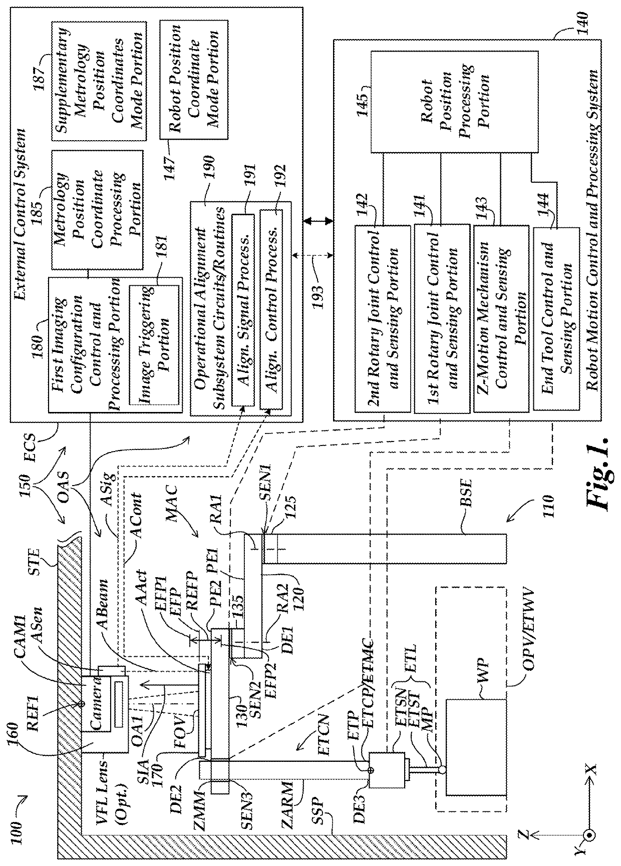
[0038]FIG. 1 is a block diagram of a first exemplary implementation of a robot system 100 including an articulated robot 110 and a supplementary metrology position coordinates determination system 150. The supplementary metrology position coordinates determination system 150 is shown to include a first exemplary implementation of an operational alignment subsystem OAS comprising at least an alignment sensor ASen connected to operational alignment subsystem processing circuits / routines 190, as described in greater detail below.
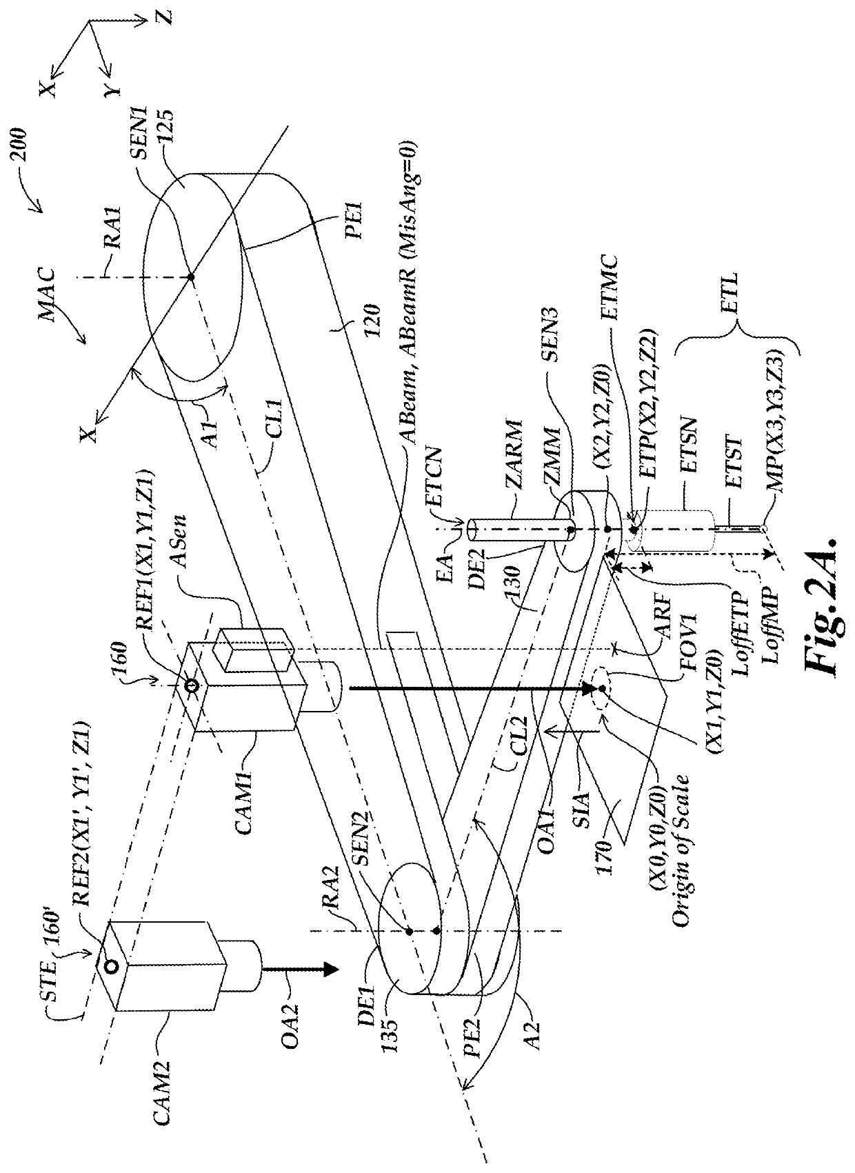
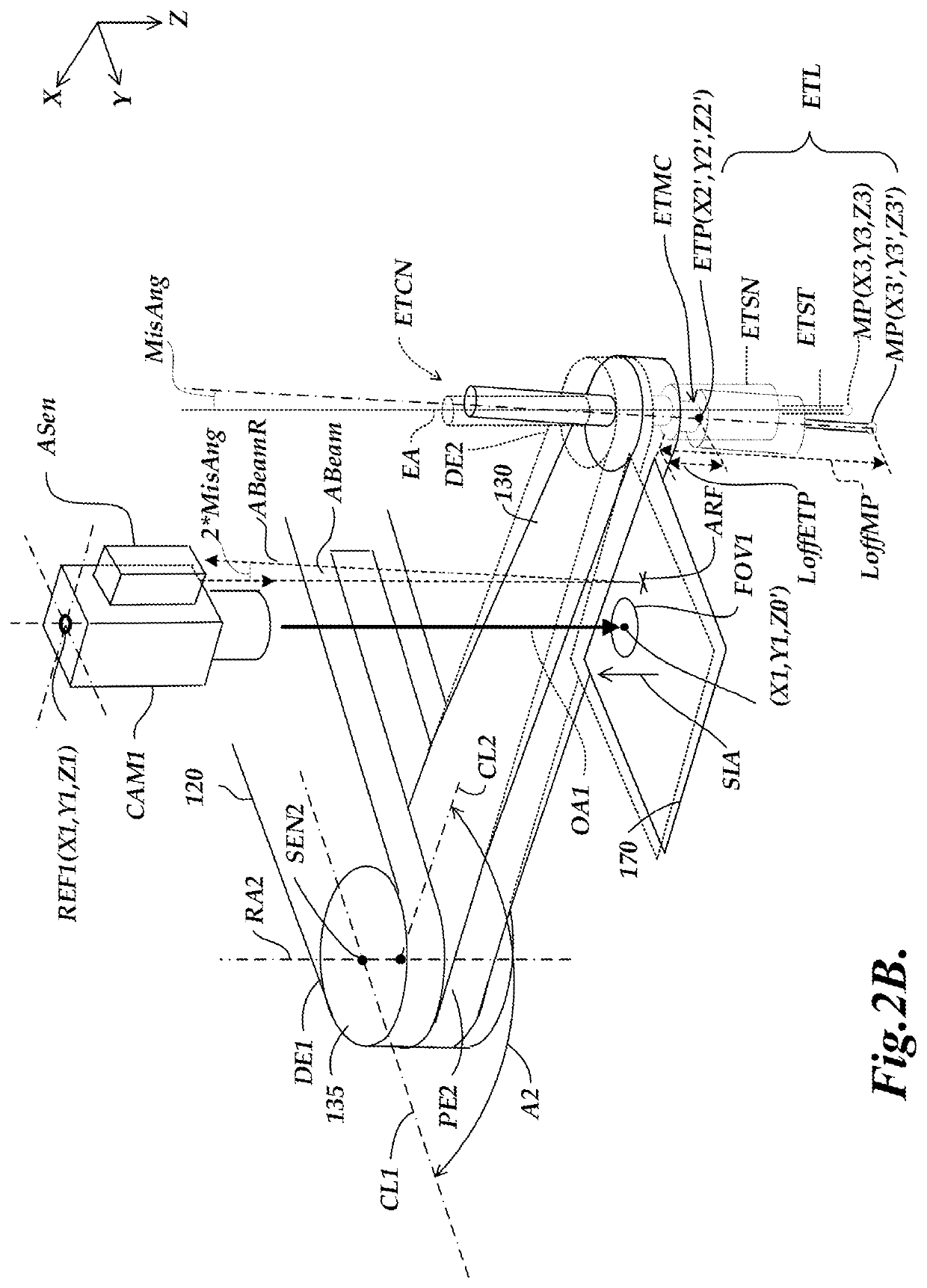
[0039]The articulated robot 110 includes first and second arm portions 120 and 130, first and second rotary joints 125 and 135, position sensors SEN1 and SEN2, an end tool configuration ETCN, and a robot motion control and processing system 140. The first arm portion 120 is mounted to the first rotary joint 125 at a proximal end PE1 of the first arm portion 120. The first rotary joint 125 (e.g., located at an upper end of a supporting base portion BSE) has a ro...
PUM
 Abstract
Description
Claims
Application Information