
Light emitting element, manufacturing method thereof, and display device including the light emitting element

a technology manufacturing methods, applied in the field of light emitting elements, can solve the problems of low blue light efficiency and easy exposure of organic materials to high-temperature operating environments

Pending Publication Date: 2021-06-03
SAMSUNG DISPLAY CO LTD
View PDF0 Cites 3 Cited by
  • Summary
  • Abstract
  • Description
  • Claims
  • Application Information

AI Technical Summary

Benefits of technology

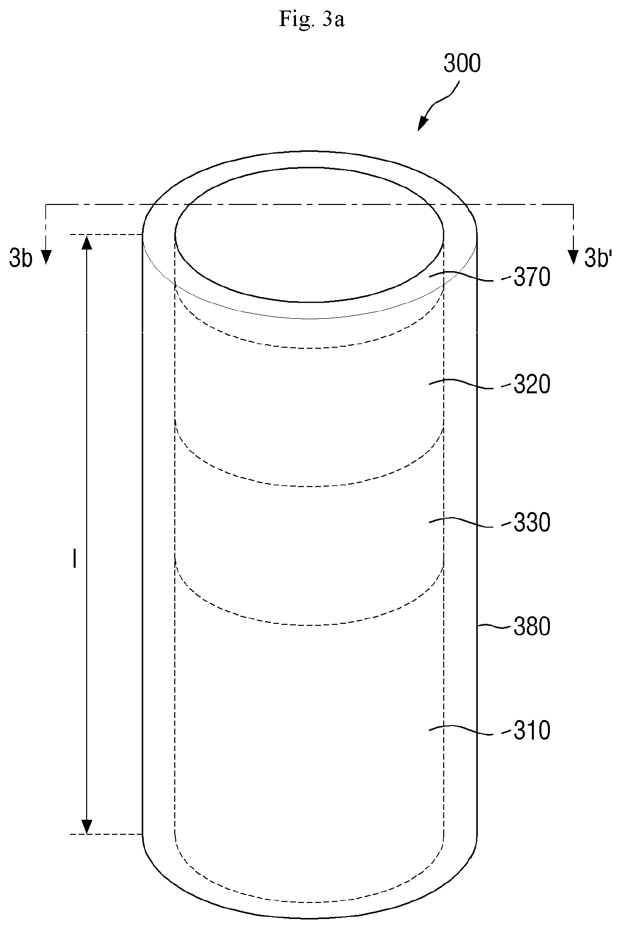
The patent text describes how to make a light emitting element with a flat surface by using a graphene layer peeling method, which separates the element from the substrate. An insulating layer is also formed on the element to prevent short circuit or open circuit issues when connected to external electrodes. This results in a light emitting element that is flat at both ends and does not require additional etching processes.

Problems solved by technology

However, it is known that the organic material is vulnerable to a high-temperature operating environment and the blue light efficiency is relatively low.
Also, in the manufacturing process, as noted as a drawback of a conventional inorganic light emitting diode, a transfer method using a dielectrophoresis (DEP) method has been developed.

Method used


Image

  • Light emitting element, manufacturing method thereof, and display device including the light emitting element
  • Light emitting element, manufacturing method thereof, and display device including the light emitting element
  • Light emitting element, manufacturing method thereof, and display device including the light emitting element

Examples


Embodiment Construction

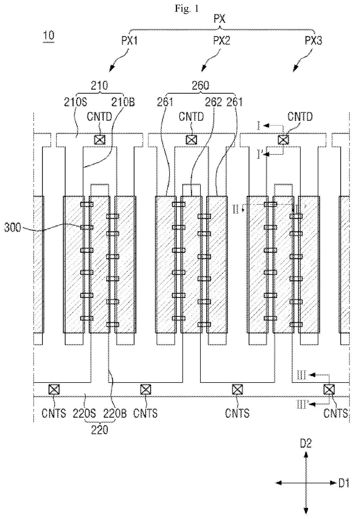
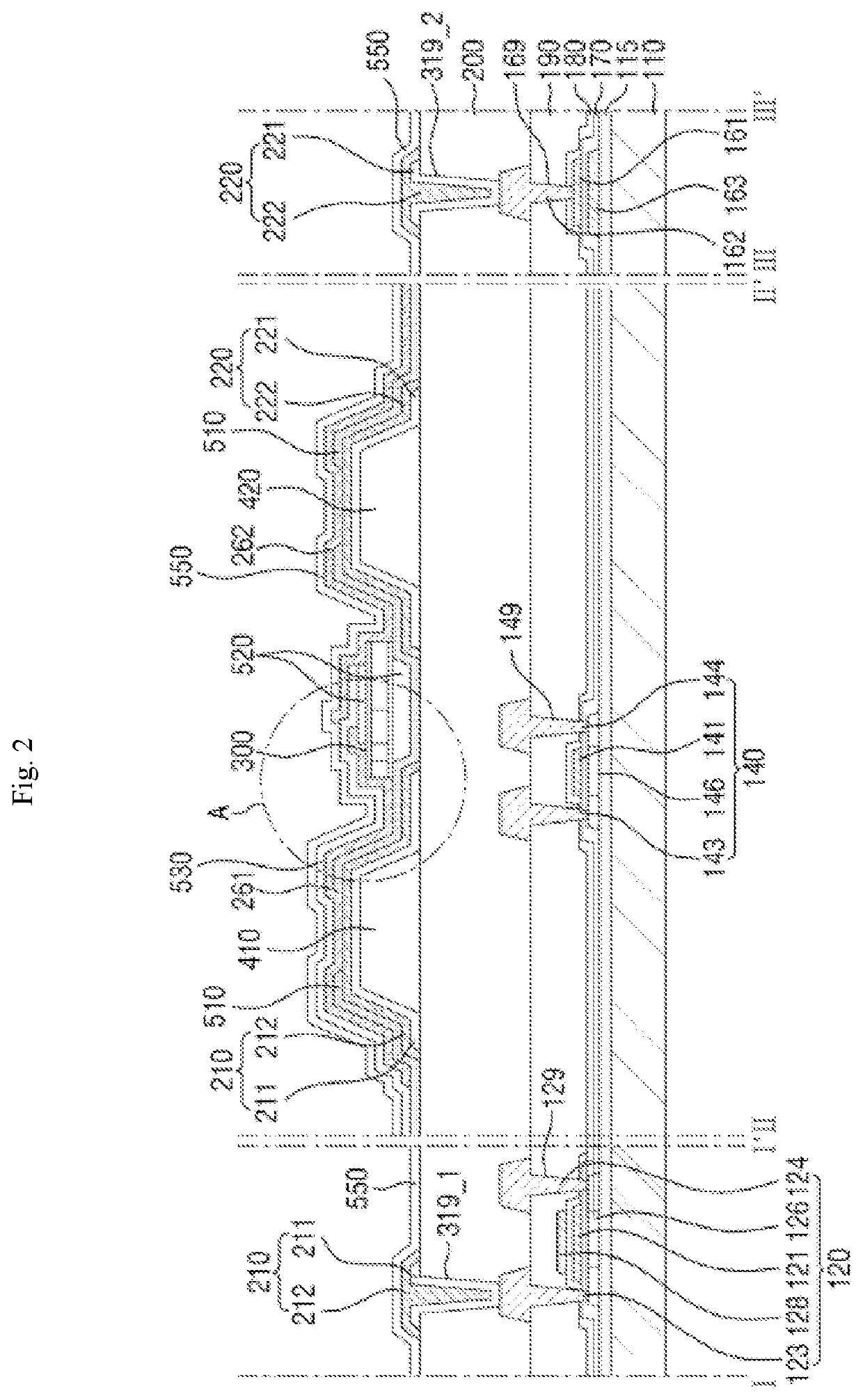
[0043]The present invention will now be described more fully hereinafter with reference to the accompanying drawings, in which preferred embodiments of the invention are shown. This invention may, however, be embodied in different forms and should not be construed as limited to the embodiments set forth herein. Rather, these embodiments are provided so that this disclosure will be thorough and complete, and will filly convey the scope of the invention to those skilled in the art.

[0044]It will also be understood that when a layer is referred to as being “on” another layer or substrate, it can be directly on the other layer or substrate, or intervening layers may also be present. The same reference numbers indicate the same components throughout the specification.

[0045]It will be understood that, although the terms “first,”“second,” etc. may be used herein to describe various elements, these elements should not be limited by these terms. These terms are only used to distinguish one el...


PUM

PropertyMeasurementUnit
surface roughnessaaaaaaaaaa
mean surface roughnessaaaaaaaaaa
lengthaaaaaaaaaa

Abstract

Provided are a light-emitting element, a manufacturing method thereof, and a display device comprising the light-emitting element. The method for manufacturing the light-emitting element comprises the steps of: preparing a lower substrate including a substrate and a buffer material layer formed on the substrate, forming a separating layer disposed on the lower substrate and including at least one graphene layer, forming an element deposition structure by depositing a first conductivity type semiconductor layer, an active material layer, and a second conductivity type semiconductor layer on the separating layer, forming an element rod by etching the element deposition structure and the separating layer in a vertical direction; and separating the element rod from the lower substrate to form a light emitting element.

Description

CROSS-REFERENCE TO RELATED APPLICATION[0001]This application is a U.S. National Phase Patent Application of Korean International Application No. PCT / KR2019 / 000537, which claims priority to Korean Patent Application No. 10-2018-0090544 filed on Aug. 3, 2018, the entire content of all of which is incorporated herein by reference.TECHNICAL FIELD[0002]The present disclosure relates to a light emitting element, a manufacturing method thereof, and a display device including the light emitting element and, in particular, to a light emitting element having an end with a smooth parting surface, a manufacturing method thereof, and a display device including the light emitting element.BACKGROUND ART[0003]The importance of display devices has steadily increased with the development of multimedia technology. Accordingly, various types of display devices such as an organic light emitting display (OLED), a liquid crystal display (LCD) and the like have been used.[0004]A display device is a device ...

Claims


Application Information

Patent Timeline
Patent Type & Authority Applications(United States)
IPC IPC(8): H01L27/15H01L33/12H01L33/22H01L33/38H01L33/40H01L33/00
CPCH01L27/156H01L33/12H01L33/0095H01L33/38H01L33/40H01L33/22H01L33/36H01L25/0753H01L33/0062H01L33/007H01L33/24H01L33/0093H01L21/02543H01L21/02579H01L21/0262
Inventor MIN, JUNG HONGKIMCHO, HYUN MINKIM, DONG UKLEE, DONG EONLEE, SEUNG ACHA, HYUNG RAE
Owner SAMSUNG DISPLAY CO LTD
Learn More