Gas flow systems for an additive manufacturing machine

a technology of additive manufacturing machine and flow system, which is applied in the direction of additive manufacturing, manufacturing environment conditioning, additive manufacturing, etc., can solve the problems of high processing complexity, insufficient scientific and technical knowledge of the production route, and inability to understand the effects of processing parameters on the microstructural evolution of the layer manufacturing process

Pending Publication Date: 2021-06-10
GENERAL ELECTRIC CO
View PDF0 Cites 4 Cited by
  • Summary
  • Abstract
  • Description
  • Claims
  • Application Information

AI Technical Summary

Problems solved by technology

Although the laser sintering and melting processes can be applied to a broad range of powder materials, the scientific and technical aspects of the production route, for example, sintering or melting rate and the effects of processing parameters on the microstructural evolution during the layer manufacturing process have not been well understood.

Method used


Image

  • Gas flow systems for an additive manufacturing machine
  • Gas flow systems for an additive manufacturing machine
  • Gas flow systems for an additive manufacturing machine

Examples


Embodiment Construction

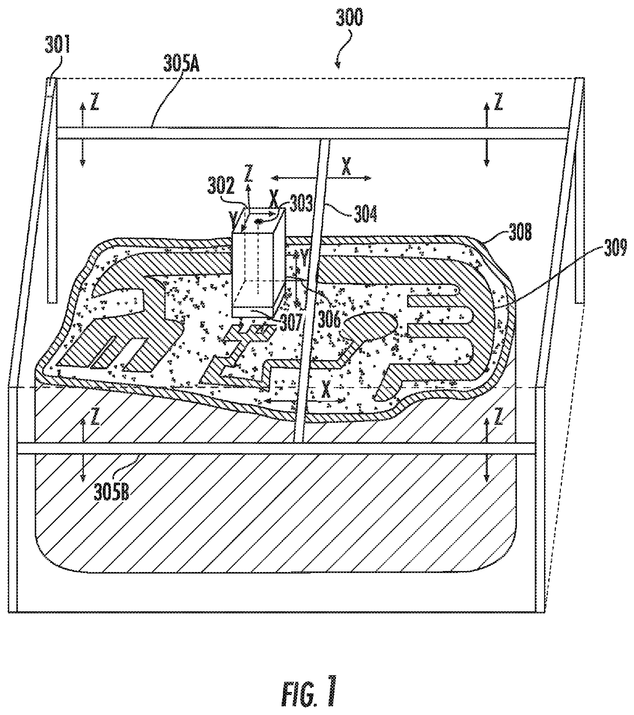
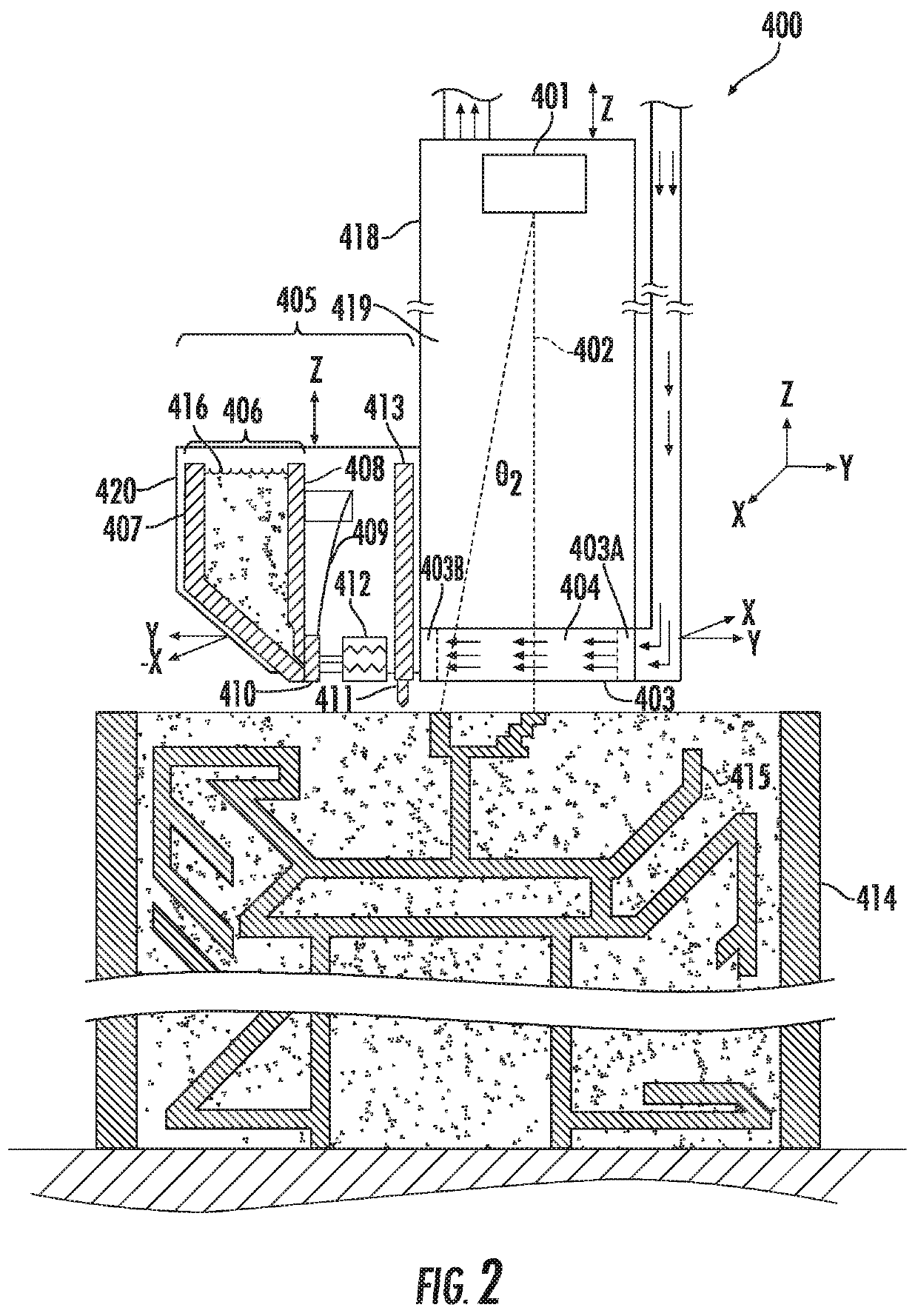
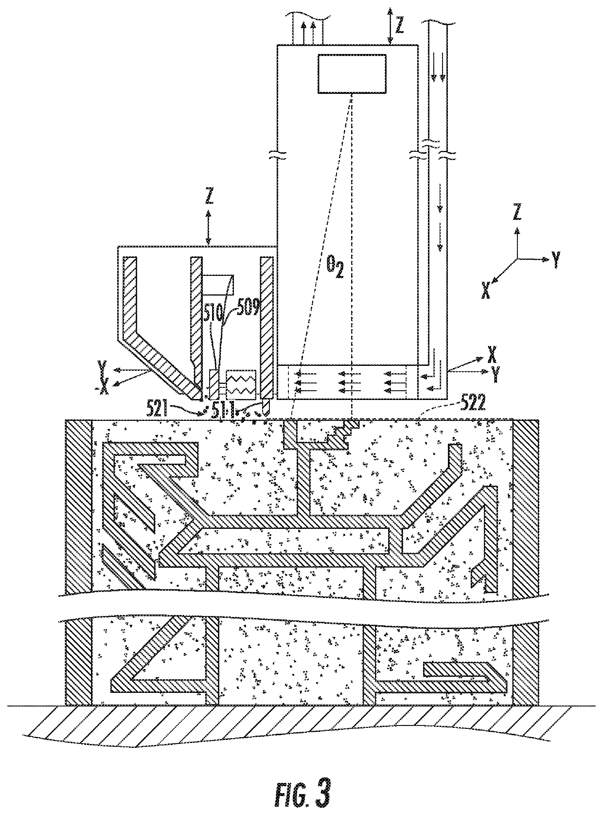
[0027]Reference now will be made in detail to embodiments of the invention, one or more examples of which are illustrated in the drawings. Each example is provided by way of explanation of the invention, not limitation of the invention. In fact, it will be apparent to those skilled in the art that various modifications and variations can be made in the present invention without departing from the scope or spirit of the invention. For instance, features illustrated or described as part of one embodiment can be used with another embodiment to yield a still further embodiment. Thus, it is intended that the present invention covers such modifications and variations as come within the scope of the appended claims and their equivalents.

[0028]As used herein, the terms “first”, “second”, and “third” may be used interchangeably to distinguish one component from another and are not intended to signify location or importance of the individual components. In addition, the terms “upstream” and “...


PUM

PropertyMeasurementUnit
Pressureaaaaaaaaaa
Sensitivityaaaaaaaaaa

Abstract

An additive manufacturing machine (900) includes a plurality of subsystems, such as a condensate evacuation subsystem (940) for removing byproducts of the additive manufacturing products near a powder bed, a closed loop subsystem (960) for cleaning contaminants from sensitive machine components (964), and/or an electronics cooling subsystem (984) for cooling an electronics compartment (980). Each subsystem (940, 960, 984) may include a dedicated gas circulation loop (942, 966, 986) that is operably coupled to a gas circulation device (944, 968, 988) for urging a clean flow of gas (946, 962, 990) to each of the subsystems (940, 960, 984) to perform a particular function.

Description

PRIORITY INFORMATION[0001]The present applicant claims priority to U.S. Provisional Patent Application Ser. No. 62 / 584,149 titled “Gas Flow Systems for an Additive Manufacturing Machine” filed on Nov. 10, 2017, the disclosure of which is incorporated by reference herein.FIELD[0002]The present disclosure generally relates to methods and systems adapted to perform additive manufacturing (AM) processes, for example by direct melt laser manufacturing (DMLM), on a larger scale format.BACKGROUND[0003]Additive manufacturing (AM) processes generally involve the buildup of one or more materials to make a net or near net shape (NNS) object, in contrast to subtractive manufacturing methods. Though “additive manufacturing” is an industry standard term (ISO / ASTM52900), AM encompasses various manufacturing and prototyping techniques known under a variety of names, including freeform fabrication, 3D printing, rapid prototyping / tooling, etc. AM techniques are capable of fabricating complex componen...

Claims


Application Information

Patent Timeline
IPC IPC(8): B22F10/50B22F10/28B22F12/49B22F12/70B22F10/77B33Y10/00B33Y30/00
CPCB22F10/50B22F10/28B22F12/49B22F12/70B22F2201/02B33Y10/00B33Y30/00B22F2201/11B22F10/77B29C64/153B29C64/371B22F10/32B22F12/67B22F10/14B22F10/322B22F12/20B22F12/22B22F10/25
Inventor MAMRAK, JUSTINREDDING, MACKENZIE RYAN
Owner GENERAL ELECTRIC CO
Why Eureka
Try Eureka