Electrical amplifier

a technology of amplifiers and amplifiers, applied in amplifiers with semiconductor devices/discharge tubes, amplifier modifications to reduce non-linear distortion, amplifier etc., can solve the problems of increasing the difficulty of realizing low-power amplifiers and driving circuits with high bandwidth, increasing power consumption, and reducing bandwidth. , to achieve the effect of reducing stability problems and large bandwidth

Active Publication Date: 2021-06-17
SICOYA GMBH
View PDF8 Cites 3 Cited by
  • Summary
  • Abstract
  • Description
  • Claims
  • Application Information

AI Technical Summary

Benefits of technology

[0009]The above exemplary embodiment of the invention may provide a large bandwidth and reduced stability issues. The basic idea is to use a negative capacitance that may neutralize not only the parasitic capacitance of the transistors of the preamplifier but also the load capacitance of the subsequent downstream amplifier stage.

Problems solved by technology

Fast analog drivers are critical components in high-speed optical transceivers; nonetheless, with increasing data rates beyond 40 Gb / s, it has become increasingly difficult to realize low-power amplifiers and driving circuits with high bandwidth.
This problem is further exacerbated by the optical modulators that require large driving currents or large voltage swing to achieve the necessary speed, which, in turn, entails either large output buffers or large gain stages, both of which resulting in higher power consumption and decreased bandwidth.
The main disadvantage of using the FFE approach and the CTLE approach is that both reduce the low-frequency gain, thus bandwidth enhancement comes at the expense of the electro-optical effect.
Since the NMC is based on a positive feedback created by the cross-connected capacitors, stability however is always an issue.

Method used


Image

  • Electrical amplifier
  • Electrical amplifier
  • Electrical amplifier

Examples


Embodiment Construction

[0069]The preferred embodiments of the present invention will be best understood by reference to the drawings. It will be readily understood that the present invention, as generally described and illustrated in the figures herein, could vary in a wide range. Thus, the following more detailed description of the exemplary embodiments of the present invention, as represented in the figures, is not intended to limit the scope of the invention, as claimed, but is merely representative of presently preferred embodiments of the invention.

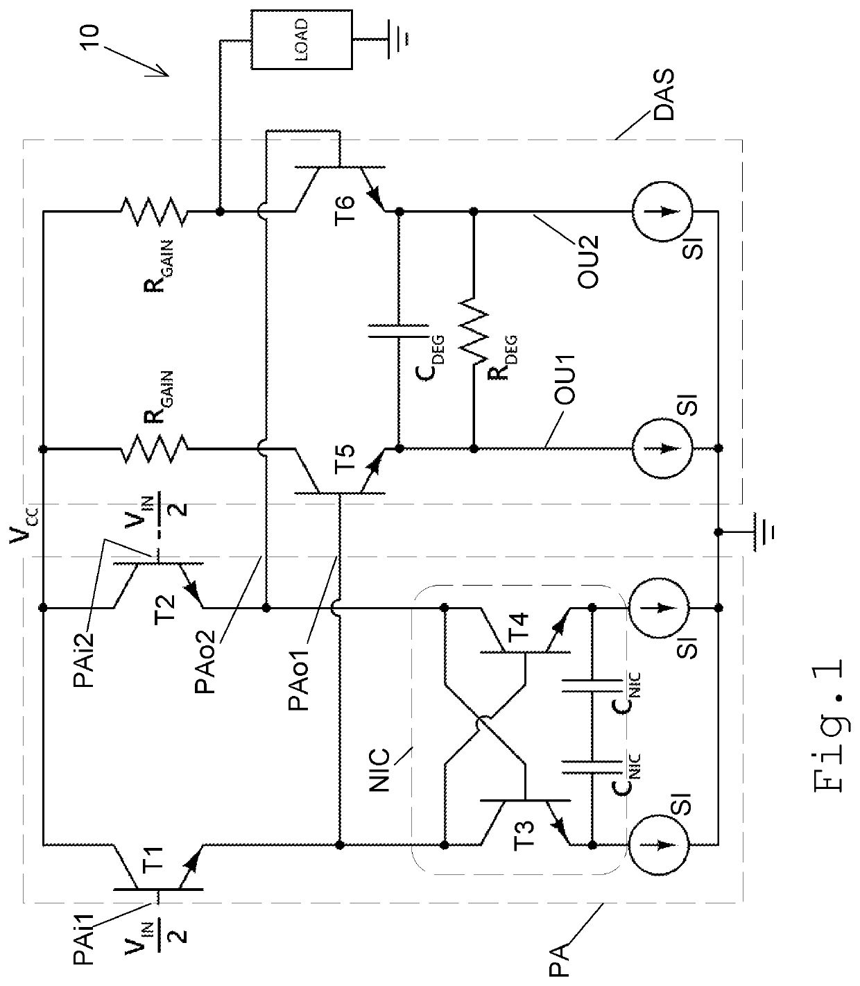
[0070]FIG. 1 shows a first embodiment of an electrical amplifier 10 according to the present invention which is provided with a supply voltage Vcc.

[0071]The amplifier 10 comprises a differential preamplifier PA having a first output port PAo1 and a second output port PAo2.

[0072]A downstream amplifier stage DAS comprises a first output unit OU1 and a second output unit OU2. The first output unit OU1 is connected to the first output port PAo1 of the differen...


PUM


Abstract

An exemplary embodiment of the invention relates to an electrical amplifier comprising a differential preamplifier having a first output port and a second output port; and a downstream amplifier stage having a first output unit and a second output unit; wherein the first output unit is connected to the first output port of the differential preamplifier and the second output unit is connected to the second output port of the differential preamplifier; and wherein a negative impedance converter is electrically located in at least one of said differential preamplifier and said downstream amplifier stage.

Description

[0001]The invention relates to electrical amplifiers as well as devices that comprise electrical amplifiers and modulators.BACKGROUND OF THE INVENTION[0002]Fast analog drivers are critical components in high-speed optical transceivers; nonetheless, with increasing data rates beyond 40 Gb / s, it has become increasingly difficult to realize low-power amplifiers and driving circuits with high bandwidth. This problem is further exacerbated by the optical modulators that require large driving currents or large voltage swing to achieve the necessary speed, which, in turn, entails either large output buffers or large gain stages, both of which resulting in higher power consumption and decreased bandwidth.[0003]Several equalization techniques can be employed to extend the bandwidth of the optical modulator, such as feed-forward equalization (hereinafter referred to as FFE approach) or continuous-time linear equalization (hereinafter referred to as CTLE approach), with the latter being less p...

Claims


Application Information

Patent Timeline
Patent Type & Authority Applications(United States)
IPC IPC(8): H03F3/45H03F1/32H03F1/02H03F1/30H03F1/42
CPCH03F3/45076H03F1/3211H03F1/0205H03F1/302H03F2203/45034H03F1/307H03F2203/45116H03F2203/45154H03F2203/45112H03F1/42H03F3/45071H03F3/45098H03F2203/45612H03F2203/45576H03F2203/45562H03F2200/369H03F2203/45644
Inventor BRONZI, DANILO
Owner SICOYA GMBH
Why Eureka
Try Eureka