Thermal radiation loss reduction in a parabolic trough receiver by the application of a cavity mirror and a hot mirror coating

a parabolic trough and thermal radiation loss technology, applied in solar heat systems, solar ray transmission and prevent heat radiation, light and heating apparatus, etc., can solve the problems of thermal heat loss dominance and the methods for reducing heat loss are far from ideal, and achieve the effect of reducing thermal radiation loss

Pending Publication Date: 2021-06-24
UNIVERSITY OF THE WITWATERSRAND
View PDF13 Cites 1 Cited by
  • Summary
  • Abstract
  • Description
  • Claims
  • Application Information

AI Technical Summary

Benefits of technology

[0006]It is also an object of the invention to provide a method of reducing thermal radiation loss from a parabolic trough receiver which will be a useful alternative to existing methods. It is yet another object of the invention to provide a parabolic trough receiver which will be a useful alternative to existing receivers.

Problems solved by technology

A significant drawback of this know design is that it has to be designed carefully and in such a way so as to minimize the energy losses.
It is known that thermal heat losses start to dominate at high receiver temperatures and the dominant heat losses occurring at high temperatures are due to the thermal emission (IR) from the receiver unit.
However, these known methods to decrease the heat losses are far from ideal as significant heat loss still occur.

Method used


Image

  • Thermal radiation loss reduction in a parabolic trough receiver by the application of a cavity mirror and a hot mirror coating
  • Thermal radiation loss reduction in a parabolic trough receiver by the application of a cavity mirror and a hot mirror coating
  • Thermal radiation loss reduction in a parabolic trough receiver by the application of a cavity mirror and a hot mirror coating

Examples


Embodiment Construction

[0043]Before any embodiments of the invention are explained in detail, it is to be understood that the invention is not limited in its application to the details of construction and the arrangement of components set forth in the following description or illustrated in the following drawings. The invention is capable of other embodiments and of being practiced or of being carried out in various ways. Also, it is to be understood that the phraseology and terminology used herein is for the purpose of description and should not be regarded as limiting. The use of “including,”“comprising,” or “having” and variations thereof herein is meant to encompass the items listed thereafter and equivalents thereof as well as additional items. Unless specified or limited otherwise, the terms “mounted,”“connected,”“supported,” and “coupled” and variations thereof are used broadly and encompass both direct and indirect mountings, connections, supports, and couplings and are thus intended to include di...


PUM


Abstract

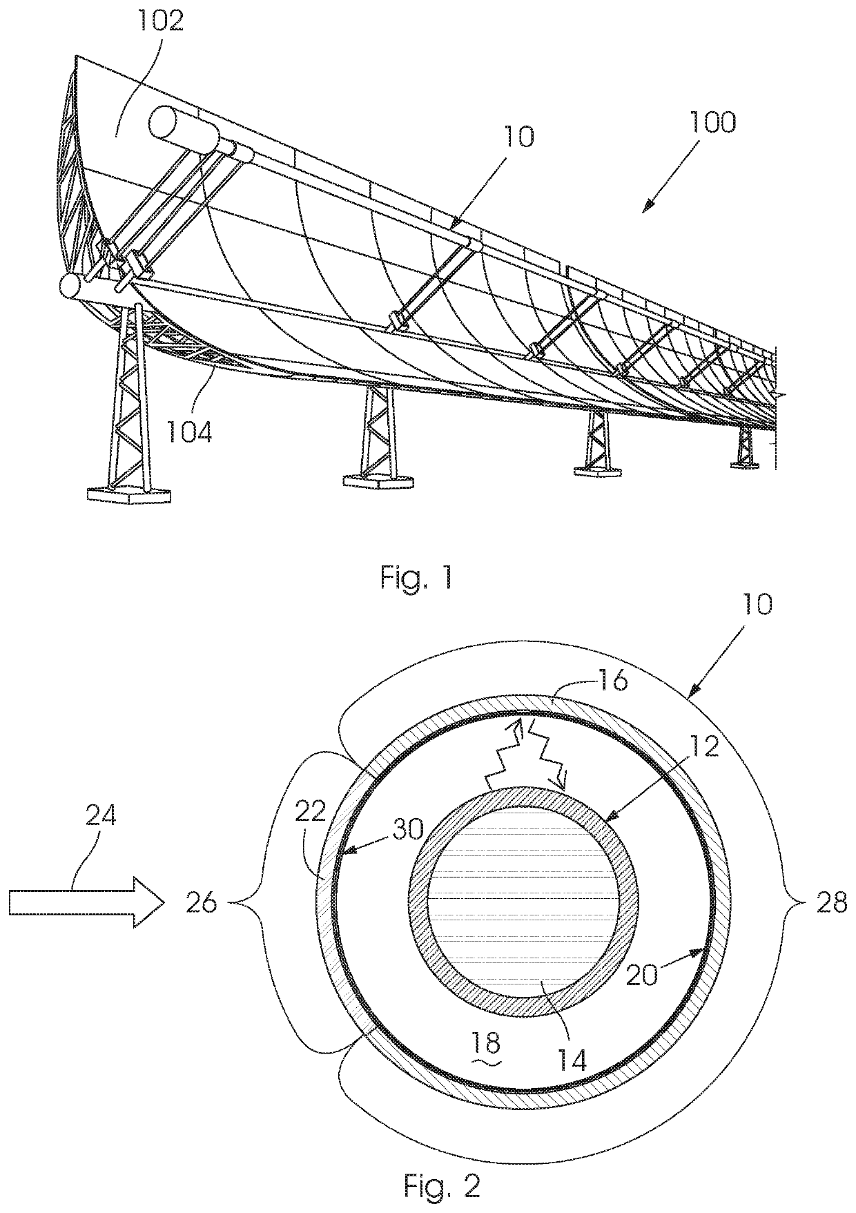
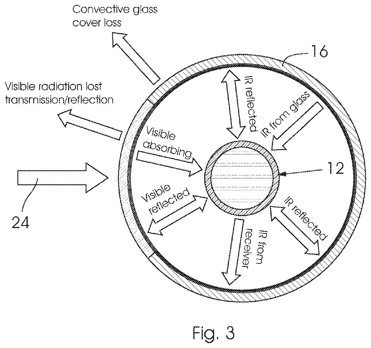
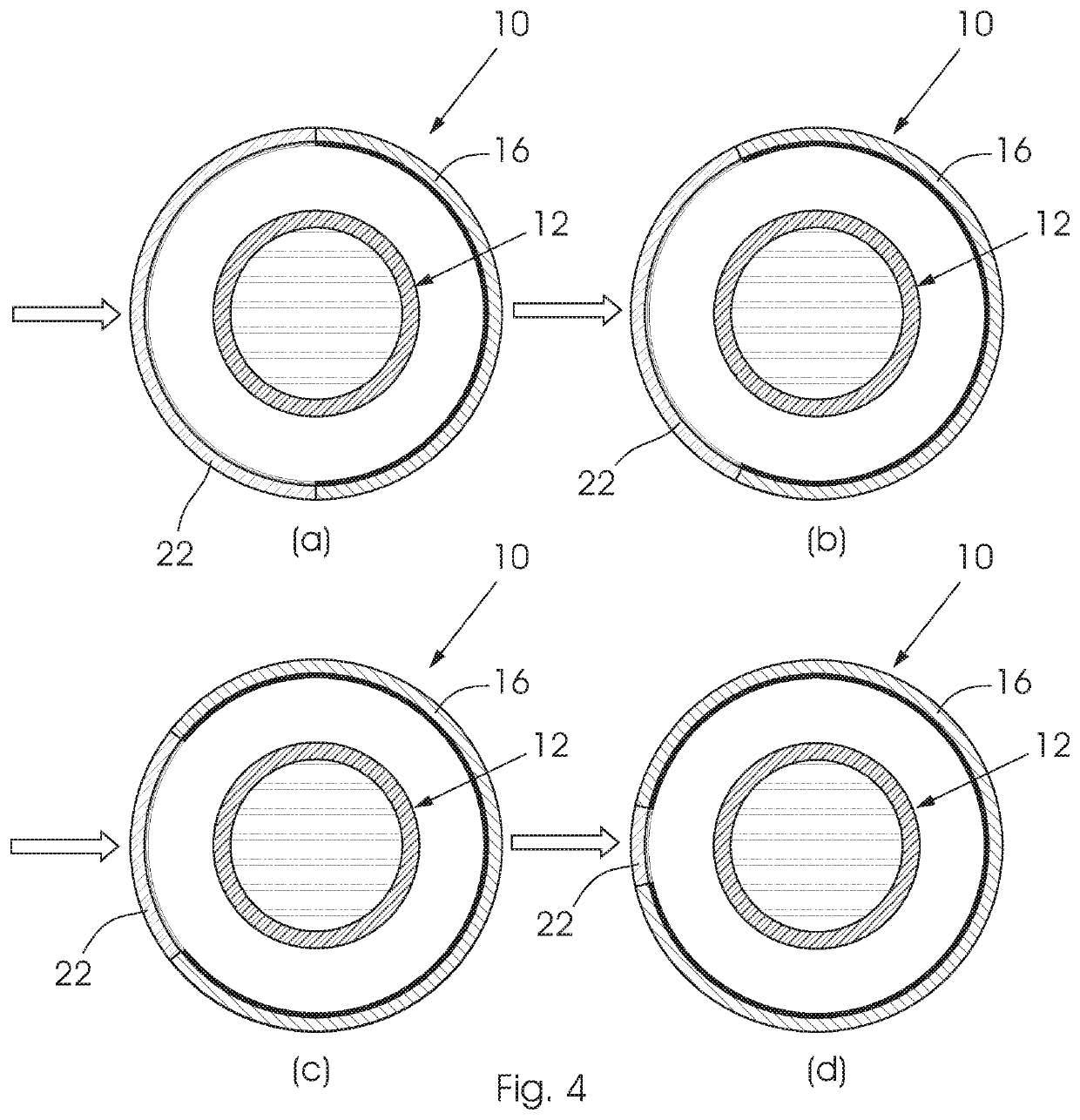
This invention concerns a receiver unit (10) for a parabolic trough solar plant. The receiver unit (10) has a conduit (12) for conveying a heat transfer fluid (14) and a cover (16), which is located about the conduit (12) such that a vacuum is formed between the conduit and the cover. The conduit (12) is designed to absorb thermal radiation. The cover (16) has a first portion (26) defining a window (22) through which incoming solar radiation (24) passes into the vacuum and onto the conduit (12) and a second portion (28) carrying a reflective surface (20) so as to reflect thermal radiation back onto the conduit (12). The invention also concerns a method of reducing thermal radiation loss from a parabolic trough receiver.

Description

BACKGROUND TO THE INVENTION[0001]THIS invention relates to a method of reducing thermal radiation loss from a parabolic trough receiver. In particular, but not exclusively, the invention relates to a method of reducing thermal radiation loss from a parabolic trough receiver by the application of a cavity mirror and a hot mirror coating. The invention further relates to a receiver unit including a cavity mirror and a hot mirror coating.[0002]Parabolic trough mirror plants are well known in the industry and are typically used to convert solar energy to heat, which can be used either directly in industrial processes, or for electricity generation. In a typical parabolic through mirror design solar radiation is focused onto a linear focal line aimed at a receiver unit. The receiver unit heats up and, in turn, imparts a large portion of its heat to a heat transfer fluid (HTF) circulating within the receiver unit. In a typical design the receiver unit comprises a blackened absorber pipe (...

Claims


Application Information

Patent Timeline
Patent Type & Authority Applications(United States)
IPC IPC(8): F24S10/40F24S20/20F24S80/56
CPCF24S10/45F24S80/56F24S20/20Y02E10/44
Inventor MOHAMAD, KHALEDFERRER, PHILLIPE
Owner UNIVERSITY OF THE WITWATERSRAND
Why Eureka
Try Eureka