Pipeline heat preservation structure

A technology of pipeline insulation and pipeline outer wall, which is applied in pipeline protection, thermal insulation, and pipeline protection through thermal insulation, etc., can solve problems such as unfavorable environmental protection and long degradation time of fiber materials.

Pending Publication Date: 2020-10-20
NANTONG JIANGSHAN AGROCHEM & CHEM LIMITED LIABILITY
View PDF0 Cites 0 Cited by
  • Summary
  • Abstract
  • Description
  • Claims
  • Application Information

AI Technical Summary

Problems solved by technology

The currently known treatment method is landfill degradation, but this method is not ...

Method used


Image

  • Pipeline heat preservation structure
  • Pipeline heat preservation structure
  • Pipeline heat preservation structure

Examples


preparation example Construction

[0046] In the present invention, the preparation method of the heat insulation board includes the following steps:

[0047] (1) Mix silicon dioxide, aluminum oxide, silicon carbide, fiber and silica fume evenly, leave to exhaust to obtain a mixed powder; then introduce the mixed powder into a mold, dry press and form it, and obtain an insulating core material;

[0048] (2) Spray the silicon solution on the surface of the insulation core material, and dry to obtain the insulation core layer;

[0049] (3) Packing the thermal insulation core layer with packaging materials, and the product is obtained.

[0050] In a preferred embodiment, the source of the silica sol is not particularly limited, and all commercially available silica sols are suitable for the present invention.

[0051] In a preferred embodiment, the packaging material is not particularly limited, and organic polymer films, glass fiber cloth, aluminum foil fiber cloth and the like can be mentioned.

[0052] In a mor...

Embodiment 1

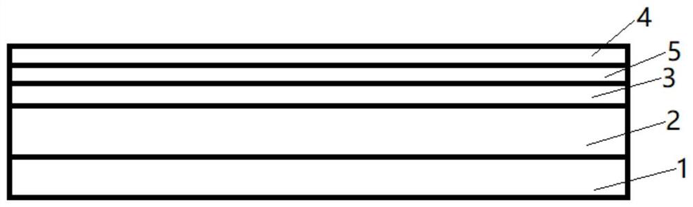
[0073] Embodiment 1 provides a kind of pipe insulation structure, such as figure 1 As shown, the pipeline insulation structure is sequentially provided with a heat insulation layer 2, a fixed layer 3, a reflection layer 5 and a protective layer 4 from the pipeline outer wall 1; the heat insulation layer 2 includes two layers of heat insulation boards with a thickness of 20mm; The two-layer insulation board adopts the method of staggered stitching; the fixed layer 3 is glass ribbon; the reflection layer 5 is aluminum foil; the protective layer 4 is iron sheet; connection; the fixed layer 3 is wrapped on the heat insulating layer 2; the reflective layer 5 is wrapped on the fixed layer 3; the protective layer 4 is wrapped on the reflective layer 5.

[0074] The raw materials for the preparation of the thermal insulation board include the following components: 70 parts of silicon dioxide, 20 parts of aluminum oxide, 20 parts of silicon carbide, 15 parts of fiber, 20 parts of silic...

Embodiment 2

[0078] The difference between embodiment 2 and embodiment 1 is that no reflective layer is included.


PUM

PropertyMeasurementUnit
Thicknessaaaaaaaaaa
Thicknessaaaaaaaaaa

Abstract

The invention relates to the technical field of pipeline heat preservation, in particular to a pipeline heat preservation structure. The pipeline heat preservation structure is characterized in that aheat insulation layer 2, a fixing layer 3 and a protective layer 4 are sequentially arranged outwards from an outer wall 1 of a pipeline. According to the pipeline heat preservation structure, the heat insulation layer is formed by splicing heat insulation plates which are prepared from nano powder, and the thickness of the heat insulation layer is 5-50 mm; the fixing layer 3 is composed of glassfiber strips and plays a role in fixing the heat insulation plates; a reflecting layer 5 is aluminum foil, the mirror surface of the reflecting layer 5 can reflect infrared rays to further improve the heat insulation effect; and the protective layer 4 is metal or metal alloy, two metal skins matched with the model of the pipeline are buckled up and down on the steam pipeline, the steam pipeline is just matched and connected with the metal skins, and the rivet fixing is reduced. The pipeline heat preservation structure has the advantages of being thin in thickness, easy to construct, environment-friendly in construction, long in service life, strong in stability, free of recovery cost and the like.

Description

technical field [0001] The invention relates to the technical field of pipeline insulation, in particular to a pipeline insulation structure. Background technique [0002] Most of the existing thermal insulation systems for pipelines use an insulation layer made of aluminum silicate insulation materials such as mineral wool or rock wool, which is directly integrally formed outside the pipeline. In order to achieve a better thermal insulation effect, the thickness of the insulation layer arranged outside the pipeline is relatively large, which brings difficulties to the transportation and installation of the pipeline. Moreover, when the insulation layer of the pipeline has problems such as damage that affects the insulation effect, it is often necessary to replace the entire insulation pipe, which not only increases the manpower and material costs for maintenance, but also causes a lot of waste. [0003] Moreover, aluminum silicate insulation materials such as mineral wool o...

Claims


Application Information

Patent Timeline
IPC IPC(8): F16L59/02F16L59/08F16L59/12
CPCF16L59/028F16L59/029F16L59/08F16L59/12
Inventor 石进刘国栋颜卫卫徐国军
Owner NANTONG JIANGSHAN AGROCHEM & CHEM LIMITED LIABILITY
Why Eureka
Try Eureka