Eureka AIR delivers breakthrough ideas for toughest innovation challenges, trusted by R&D personnel around the world.

Patch antenna design for easy fabrication and controllable performance at high frequency bands

Pending Publication Date: 2021-07-15
JOHN MEZZALINGUA ASSOC LLC
View PDF2 Cites 0 Cited by
  • Summary
  • Abstract
  • Description
  • Claims
  • Application Information

AI Technical Summary

Benefits of technology

The present patent text describes a new type of radiator for an antenna. The radiator consists of a pair of PCB stims that are arranged in a cross fashion. Each PCB stem has feeder metallic traces and opponent metallic traces, which are connected by vias in the stem. The radiator also has a radiator plate that is mechanically attached to the PCB stims. This design allows for improved performance and reliability of the antenna.

Problems solved by technology

New 3GPP bands, such as Citizens Broadband Radio Service (CBRS) spectrum (3550-3700 MHz) and Licensed Assisted Access (LAA) spectrum (5150-5350 MHz and 5470-5925 MHz) present challenges to antenna designers and manufacturers in that radiators that perform in these bands are very sensitive to manufacturing variations.
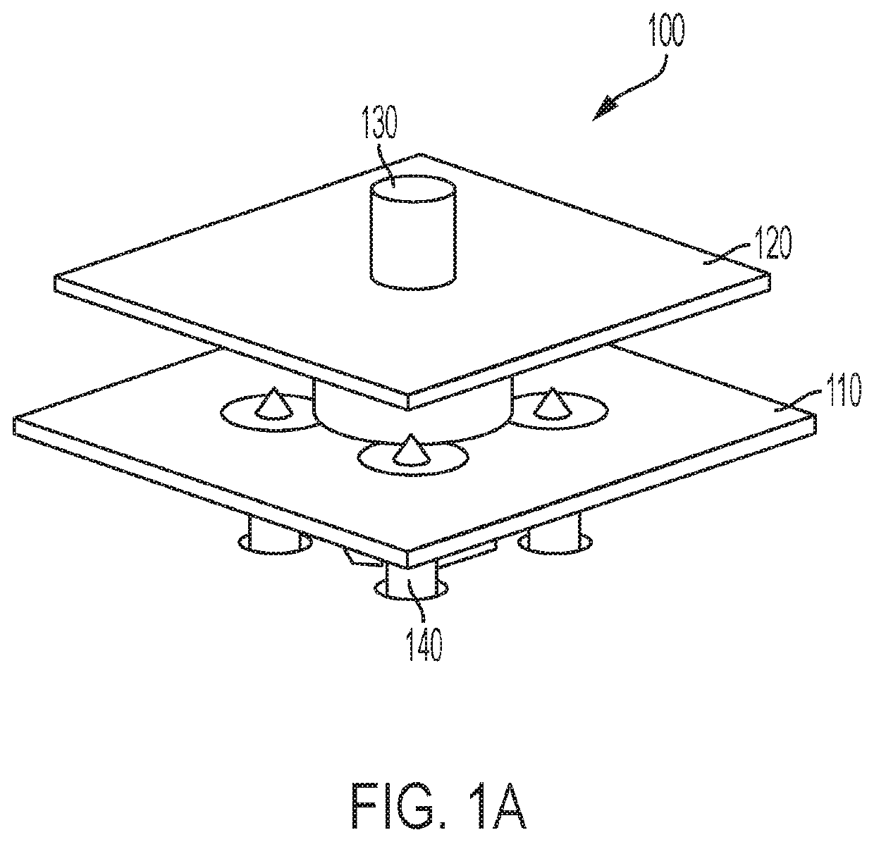
Given the shorter wavelengths corresponding to these higher frequencies, slight defects or imprecisions in solder joints or mounting of radiator plates can lead to variations that are a significant percentage of wavelength, leading to poor impedance matching.
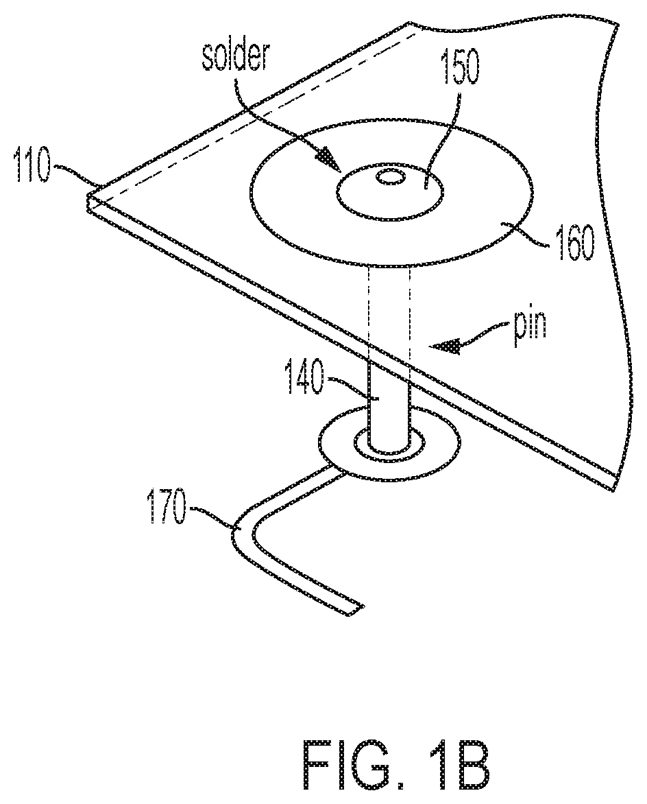
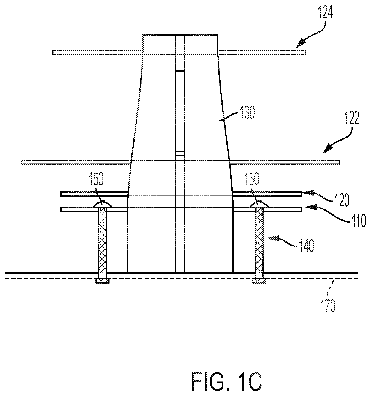
These variations in solder point 150 heights may cause considerable impedance mismatches for the conventional high frequency radiator 100.

Method used


Image

  • Patch antenna design for easy fabrication and controllable performance at high frequency bands
  • Patch antenna design for easy fabrication and controllable performance at high frequency bands
  • Patch antenna design for easy fabrication and controllable performance at high frequency bands

Examples


Embodiment Construction

[0028]Reference will now be made in detail to embodiments of the patch antenna design for easy fabrication and controllable performance at high frequency bands with reference to the accompanying figures

[0029]FIG. 2 illustrates an exemplary high frequency radiator 200 according to the disclosure, disposed on array face PCB 202. High frequency radiator 200 includes a PCB radiator plate 210 that is mounted to two PCB stems 230 that are arranged in an interlocking cross configuration. Disposed on each PCB stem 230 is a feeder metallic trace 240 and an opposing metallic trace 245, each of which is disposed on opposite sides of a corresponding PCB stem 230. Feeder metallic trace 240 is coupled to an RF feeder line (not shown) by solder joint 260.

[0030]FIG. 3 illustrates two sides of a PCB stem 230, including a front side and a back side. Disposed on the front side of PCB stem 230 are feeder metallic traces 240. Feeder metallic trace 240 has a vertical feederportion 320 and a horizontal tr...


PUM


Abstract

Disclosed is a high frequency radiator for an antenna. The high frequency radiator is formed of two interlocking PCB stems on which a radiator plate is mounted. Disposed on each of the interlocking PCB stems are two combinations of a feeder metallic trace and an opposing metallic trace, disposed on opposite sides of the PCB stem and electrically coupled together by at least one via formed in the PCB stem and a solder point within the via. This configuration of high frequency radiator is considerably cheaper to manufacture compared to conventional designs and is less susceptible to impedance matching problems resulting from inconsistent solder joint dimensions.

Description

CROSS REFERENCE TO RELATED APPLICATIONS[0001]This Application claims priority to U.S. Provisional Patent Application No. 62 / 671,706, filed May 15, 2018, which is hereby incorporated by reference in its entirety.BACKGROUND OF THE INVENTIONField of the Invention[0002]The present invention relates to wireless communications, and more particularly, to antennas that are capable of operating in high frequency ranges.Related Art[0003]As mobile telecommunications advance toward the advent of 5G, increasing demands for higher datarates, enabled by carrier aggregation, are leading to exploitation of spectrum in higher frequency ranges. New 3GPP bands, such as Citizens Broadband Radio Service (CBRS) spectrum (3550-3700 MHz) and Licensed Assisted Access (LAA) spectrum (5150-5350 MHz and 5470-5925 MHz) present challenges to antenna designers and manufacturers in that radiators that perform in these bands are very sensitive to manufacturing variations. Given the shorter wavelengths corresponding ...

Claims


Application Information

Patent Timeline
IPC IPC(8): H01Q21/08H01Q9/04
CPCH01Q21/08H01Q9/045H01Q1/246H01Q21/26H01Q9/0457H01Q9/0407H01Q1/38
Inventor JANG, TAEHEETAMBE, NIHARIKARAGOS, JORDANSUNDARARJAN, NIRANJAN
Owner JOHN MEZZALINGUA ASSOC LLC
Why Eureka
Eureka Blog
Learn More