
Catheter with multifunctional microinjection-molded housing

a catheter and micro-injection technology, applied in the field of electrophysiologic (ep) catheters, to achieve the effects of simplifying the integration of electrical conductors and contacts, simplifying structure and arrangement, and facilitating multiple functions

Pending Publication Date: 2021-07-22
BIOSENSE WEBSTER (ISRAEL) LTD
View PDF9 Cites 0 Cited by
  • Summary
  • Abstract
  • Description
  • Claims
  • Application Information

AI Technical Summary

Benefits of technology

The invention is an electrophysiology catheter that has a distal electrode section with a unique structure that allows for multiple functions. The section includes a puller tensile member anchor, an electromagnetic position sensor, a force sensor, a ring electrode placement, and a simplified integration of electrical conductors and contacts. The section also includes flexible circuits for the integration of electrical conductors, which can adapt to space restrictions and eliminate the use of traditional welding processes. The flexible circuits can be more easily integrated into the section using electrical traces applied by deposition methods. The technical effect of the invention is to provide a more efficient and flexible electrophysiology catheter with multiple functions.

Problems solved by technology

Consequently, the distal electrode section is often cramped with components criss-crossing and overlapping each other, making assembly a challenge and the distal electrode section an area where damage and defects can occur.

Method used


Image

  • Catheter with multifunctional microinjection-molded housing
  • Catheter with multifunctional microinjection-molded housing
  • Catheter with multifunctional microinjection-molded housing

Examples


Embodiment Construction

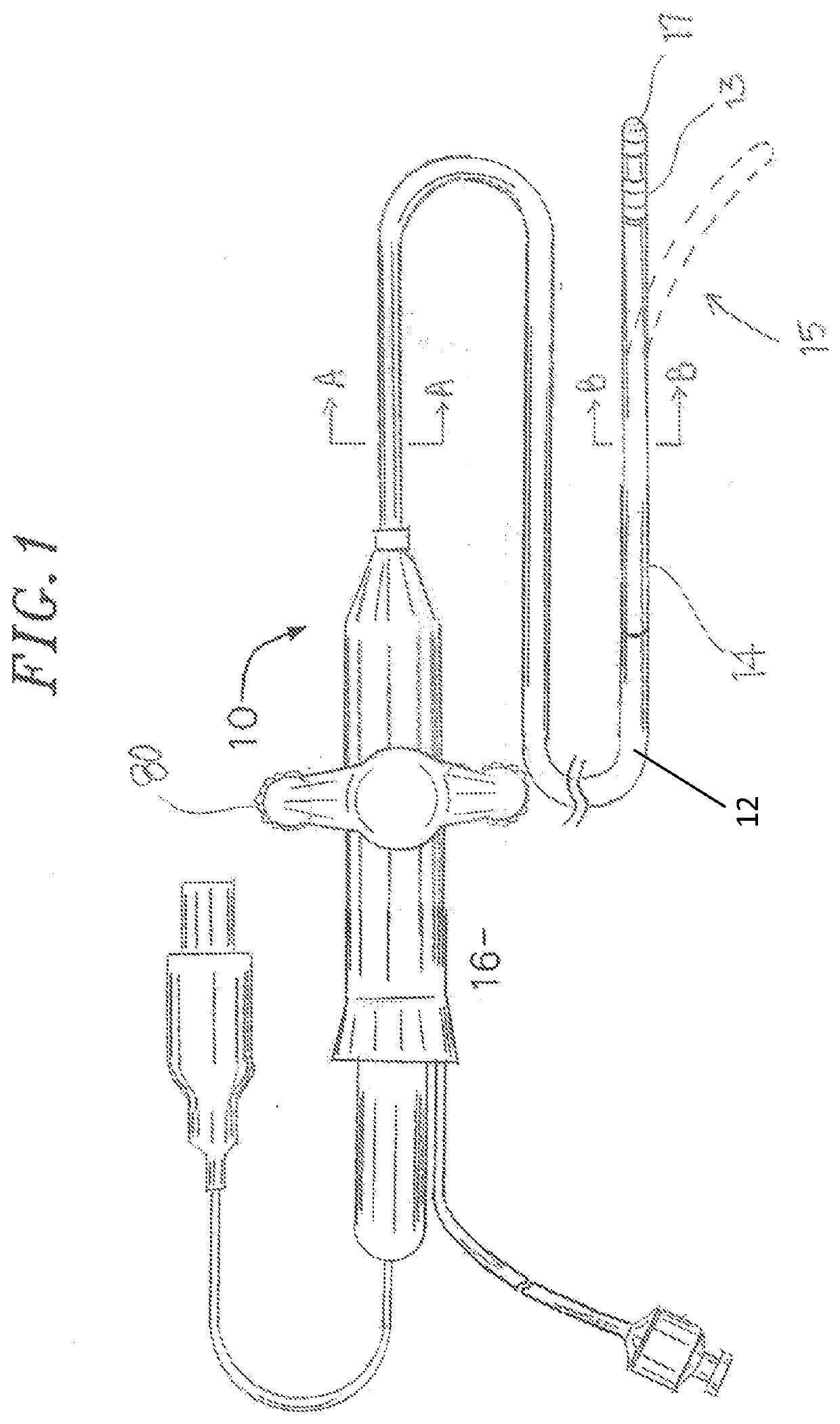
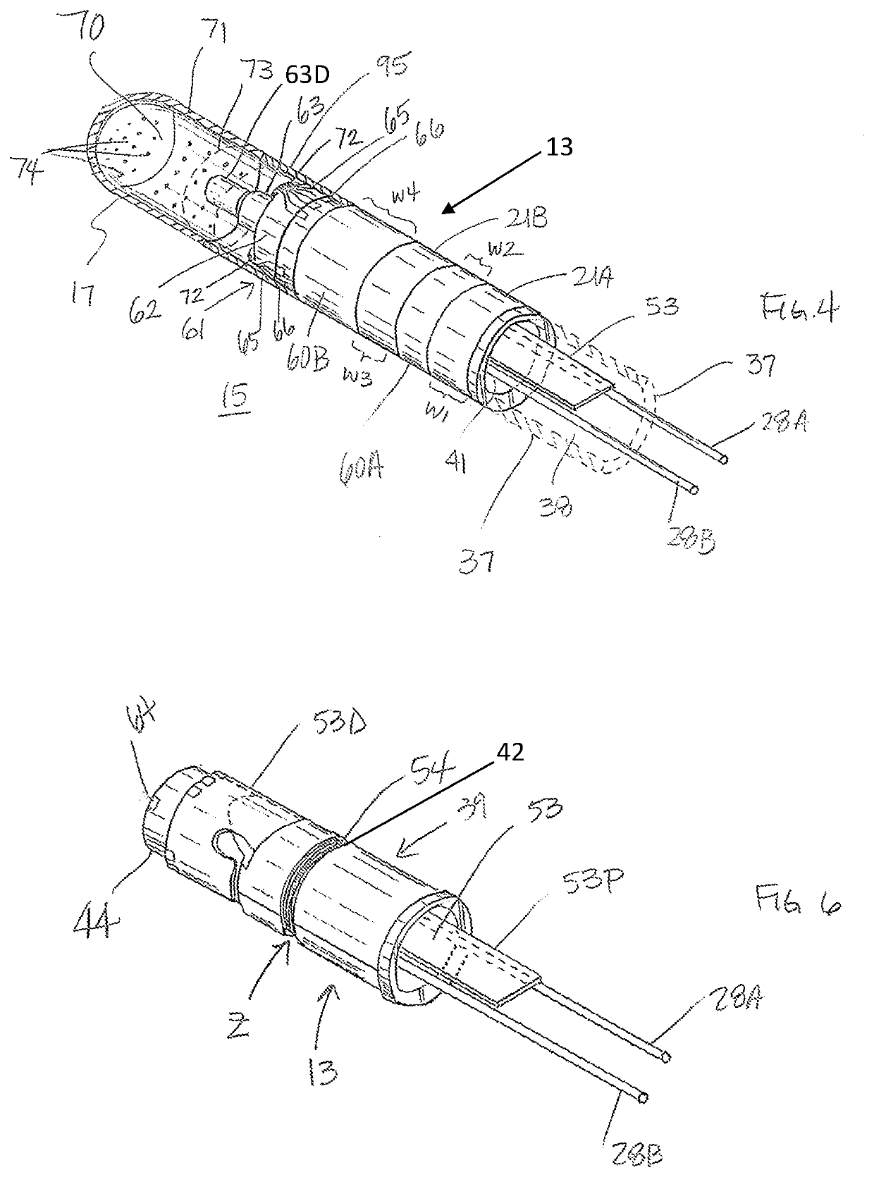
[0041]FIG. 1 illustrates an embodiment of a catheter 10 having an elongated catheter body 12 with proximal and distal ends, an intermediate deflectable section 14 at the distal end of the catheter body 12, and a distal electrode section 15 with a tip electrode 17 and a micro-injection molded, multi-functional housing 13. The catheter also includes a control handle 16 at the proximal end of the catheter body 12 for controlling bi-directional deflection of the intermediate section 14 relative to the catheter body 12.

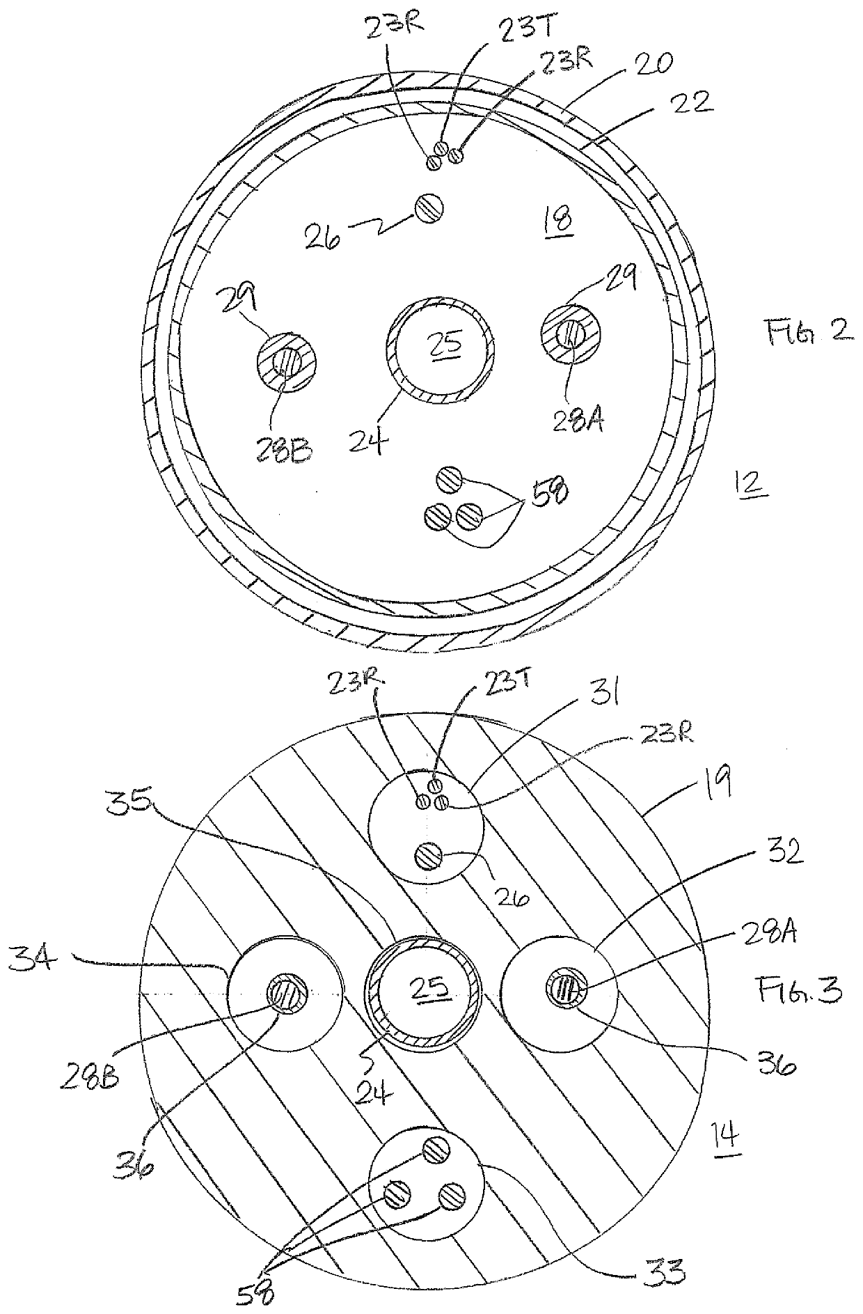
[0042]With reference to FIG. 2, the catheter body 12 comprises an elongated tubular construction having a single, axial or central lumen 18. The catheter body 12 is flexible, i.e., bendable, but substantially non-compressible along its length. The catheter body 12 can be of any suitable construction and made of any suitable material. In some embodiments, the catheter body 12 comprises an outer wall 20 made of polyurethane or PEBAX with an imbedded braided mesh of stainless...


PUM


Abstract

An electrophysiology catheter has a distal electrode section having a generally-cylindrical, hollow housing body, a lumen and an opening in a sidewall. A flex circuit has a first portion supported on the outer surface the housing body, and a second portion that extends into the lumen via the opening for connection to cables and / or wires in the lumen. The flex circuit has a first and second magnetic field sensing coil traces generally perpendicular to each other and a magnetic field sensing coil wire generally perpendicular thereto is wound around the housing body to form an x / y / z position sensor. One or more ring electrodes are carried on the housing body, separated by ring spacers. A force sensor is mounted on a distal end of the housing body, with strain gauges electrically connected to the flex circuit. The housing is configured to provide a distal anchor for a puller tensile.

Description

CROSS-REFERENCE TO RELATED APPLICATION[0001]This application is a continuation of and claims priority to and the benefit of U.S. application Ser. No. 15 / 925,521 filed Mar. 19, 2018, now U.S. Pat. No. 10,966,783, the entire contents of which are incorporated herein by reference.FIELD OF INVENTION[0002]The present invention relates to electrophysiologic (EP) catheters, in particular, EP catheters for ablating cardiac tissue.BACKGROUND[0003]Electrode catheters have been in common use in medical practice for many years. Diagnosis and treatment of cardiac arrythmias by means of electrode catheters include mapping the electrical properties of heart tissue and selectively ablating cardiac tissue by application of energy. Such ablation can cease or modify the propagation of unwanted electrical signals from one portion of the heart to another. The ablation process destroys the unwanted electrical pathways by formation of non-conducting lesions. Various energy delivery modalities have been di...

Claims


Application Information

Patent Timeline
Patent Type & Authority Applications(United States)
IPC IPC(8): A61B18/14A61B5/00A61M25/00A61B5/296
CPCA61B18/1492A61B5/6852A61B2090/065A61M25/0068A61M25/0043A61B18/14A61B18/12A61B2018/00904A61B2018/00351A61B2018/00577A61B2018/00029A61B2218/002A61B2017/00318A61B2090/064A61M25/0136A61B2017/00017A61B2017/00243A61B2018/00005A61B2018/00011A61B5/0044A61B5/0215A61B2017/00053A61B5/0082A61M25/01A61B2018/1467A61M25/003A61B2017/00323A61B5/004A61B2018/00571A61M2025/0036A61B2017/003A61B2018/0091A61B18/1402A61B5/05
Inventor SCHULTZ, JEFFREY WILLIAM
Owner BIOSENSE WEBSTER (ISRAEL) LTD
Learn More