Laser microscope with ablation function

a laser microscope and function technology, applied in the field of laser microscopes, can solve the problems of destroying samples by heating and requiring a very high technical effort, and achieve the effects of saving time and resources, high contrast, and high precision

Active Publication Date: 2021-07-22
FRIEDRICH SCHILLER UNIV JENA +1
View PDF0 Cites 0 Cited by
  • Summary
  • Abstract
  • Description
  • Claims
  • Application Information

AI Technical Summary

Benefits of technology

[0067]The exemplary workflow can also be used for important operations on physiologically important structures, as it can be operated with a high precision, and the targeted structures can be displayed in high contrast. There is no need to utilize contrast agents.
[0068]Since the examination can be carried out directly in the

Problems solved by technology

Permanently operating at such intensity may require a very high techni

Method used


Image

  • Laser microscope with ablation function
  • Laser microscope with ablation function
  • Laser microscope with ablation function

Examples


Embodiment Construction

)

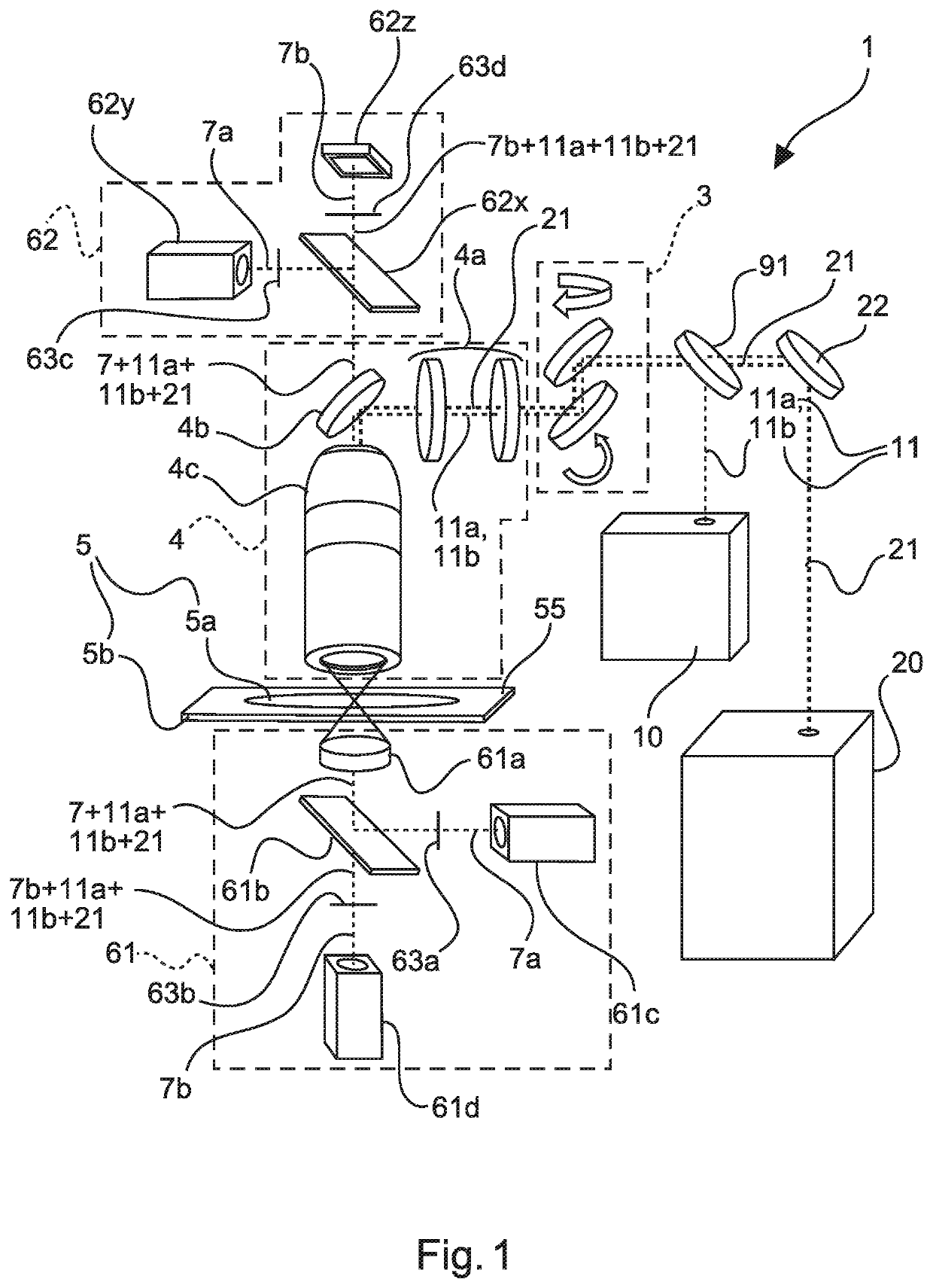
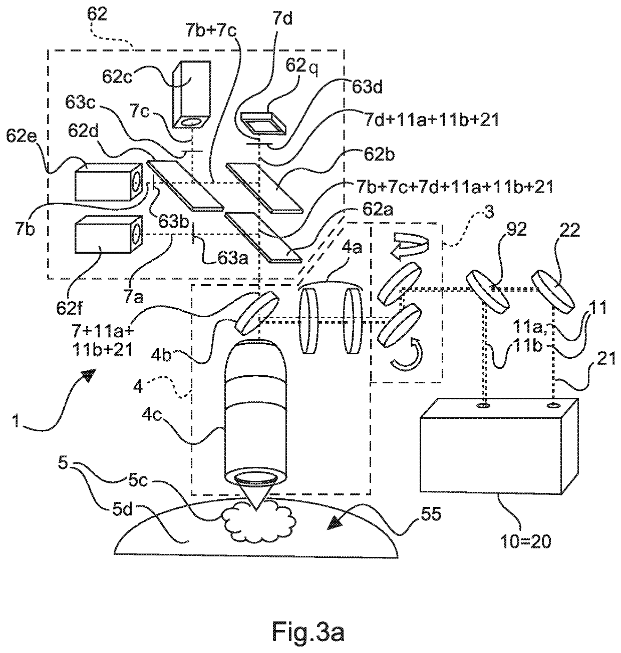
[0009]According to the exemplary embodiment of the present disclosure, a laser microscope with a laser source can be provided. For example, such exemplary laser microscope can comprise a first laser source, which can be configured to emit at least one excitation beam (which can be pulsed), a scanning optical configuration which can be configured to scan the excitation beam.

[0010]over the surface of a sample, a focussing optical configuration, which can be configured to focus the excitation beam onto the sample, and at least one detector which can be configured to detect light emitted by the sample due to an optical effect in response to the excitation beam impacting the sample. The exemplary laser microscope can, e.g., be configured for multi modal imaging.

[0011]The exemplary optical effect can be a linear effect. The imaging procedure can take place in an accelerated manner, as an extensive amount of signal intensity is available. It can be particularly advantageous for the optica...


PUM


Abstract

An exemplary laser microscope can be provided, comprising at least one first laser source which emits at least one (e.g., pulsed) excitation beam, a scanning optical configuration (e.g., configured to scan the excitation beam over the surface of a sample), a focusing optical configuration (e.g., configured to focus the excitation beam onto the sample), and at least one detector configured to detect light emitted by the sample due to an optical effect in response to the excitation beam. A second laser source facilitates a pulsed ablation beam for a local ablation of the material of the sample. The ablation beam can be guided to the sample via the scanning and focusing optical configurations, The first and second laser sources can be fed by a mutual continuous wave pump laser- and/or a mutual pulsed pump laser. The first laser source can emit pulses with at least two different wavelengths.

Description

CROSS REFERENCE TO RELATED APPLICATION(S)[0001]This application relates to, and claims the benefit and priority from International Patent Application No., PCT / IB2017 / 052962 filed on May 19, 2017 that published as International Patent Publication No. WO 2017 / 199211 on Nov. 23, 2017, which claims the benefit and priority from German Patent Application No. 10 2016 109 3013 filed on May 20, 2016, the entire disclosures of which are incorporated herein by reference in their entireties.FIELD OF THE DISCLOSURE[0002]The present disclosure relates to a laser microscope, with which a sample can be examined by imaging, e.g., nonlinear optical, methods, as well as modified by a removal of material as well as a method for providing and / or operating the exemplary laser microscope.BACKGROUND INFORMATION[0003]For laser microscoping, a laser beam with a scanning optic can be scanned over a surface of the sample that should be examined. Thereby, the spatial resolution of the illuminated region on the...

Claims


Application Information

Patent Timeline
IPC IPC(8): G01N21/71G01N21/64G01N21/65
CPCG01N21/718G01N21/6458G01N2021/656G01N2021/655G01N21/65
Inventor POPP, JÜRGENSCHMITT, MICHEALMEYER, TOBIASNOLTE, STEFANACKERMANN, ROLANDLIMPERT, JENS
Owner FRIEDRICH SCHILLER UNIV JENA
Why Eureka
Try Eureka