Method and device for connecting composite metal foils for pouch cells with a pre-sealing tape

Pending Publication Date: 2021-07-22
VOLKSWAGEN AG
View PDF0 Cites 0 Cited by
  • Summary
  • Abstract
  • Description
  • Claims
  • Application Information

AI Technical Summary

Benefits of technology

[0025]An advantage of the present invention consists of the fact that the connection of the composite metal foil to the pre-sealing tape can be integrated into the two subsequent process steps, namely, deep drawing and severing. This entails the advantage of simplifying the production process.
[0026]In particular, it is also advantageous if, prior to the creation of the texture on the surface of the composite metal foil, the latter is inserted into a shaping device having a recess. For this purpose, the composite metal foil is placed, for example, onto a matrix, whereby the matrix has such a recess matching the shape that the finished composite metal foil or pouch foil is supposed to acquire later on. In this process, the composite metal foil can be firmly affixed in the matrix by means of a hold-down device in order to ensure that it is securely held during the processing. In this context, the hold-down device functions along the lines of a foil holder or blank holder for the pouch foil.
[0027]In particular, it is also advantageous for the texture on the composite metal foil to be created in step a) by means of an insert in the hold-down device in the shaping device. Towards this end, an insert that has been provided in the hold-down device or else a separately provided insert closes shortly before or at the end of the shaping process in order to create the envisaged texture in the composite metal foil. The texture can be created simultaneously during the severing procedure or else subsequently. For instance, the hold-down device—which is an integral part of the shaping device—can be used to affix the composite metal foil. This is done in that the composite metal foil is first placed onto the matrix. Subsequently, the hold-down device is moved in the direction of the matrix and it then presses the composite metal foil aga

Problems solved by technology

When it comes to solutions known in actual practice, the pre-sealing tapes turn out to be problematic when the arrester is being welded.
As a rule, this leads to heat input into the arrester tab, as a result of which the temperature-sensitive pre-sealing tapes can be damaged.
In order to prevent this, it is necessary to continuously and often very laboriously cool the arrester tabs and the pre-sealing tapes during the welding process.
In actual practice, however, the distance usually cannot be set to be so large since such a large distance results in a loss of valuable

Method used


Image

  • Method and device for connecting composite metal foils for pouch cells with a pre-sealing tape
  • Method and device for connecting composite metal foils for pouch cells with a pre-sealing tape
  • Method and device for connecting composite metal foils for pouch cells with a pre-sealing tape

Examples


Example

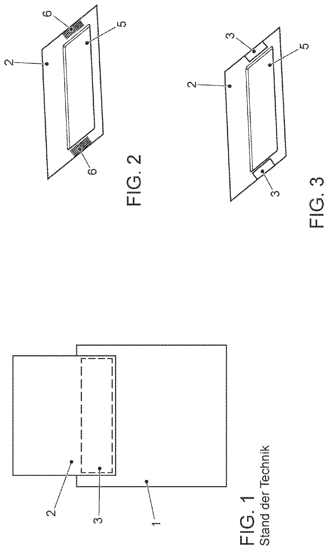
[0052]FIG. 1 shows an arrester tab 1 with a composite metal foil 2 (pouch) and a pre-sealing tape 3. The arrester tab 1 consists of an electrically conductive metal, for instance, aluminum, copper or steel and, in the finished, mounted state, it serves as a contact for a pouch cell 4 (not shown in this view). The composite metal foil 2 consists of a very thin metal layer that has been applied onto a carrier layer. The carrier layer can be made, for example, of a plastic such as polypropylene or polyethylene. According to the state of the art, in the finished, mounted state, the plastic side of the composite metal foil 2 has to be connected to the arrester tab 1, whereby the pre-sealing tape 3 is arranged between the two components in order to ensure a permanent, tight sealing of the pouch cells 4 towards the outside. This is necessary in order to prevent electrolyte from escaping or foreign matter from getting into the pouch cells 4. The arrester lugs that are likewise necessary for...


PUM


Abstract

A method for connecting a pre-sealing tape to a composite metal foil for pouch cells comprises at least the following steps: (a) creating a texture in at least a partial area of the composite metal foil; (b) applying a pre-sealing tape onto the composite metal foil, whereby the texture is at least partially covered by the pre-sealing tape; (c) connecting the pre-sealing tape to the composite metal foil to form a composite body; and (d) cutting the composite body to the predefined finished contour.

Description

CROSS REFERENCE TO RELATED APPLICATION[0001]This application claims priority from German Patent Application No. 10 2020 101 087.7, filed Jan. 17, 2020, the entire contents of which is incorporated herein by reference.FIELD OF THE INVENTION[0002]The invention relates to a method and to a device for connecting a pre-sealing tape to a composite metal foil for pouch cells.SUMMARY OF THE INVENTION[0003]The state of the art discloses several types of batteries with pouch cells which, as a rule, are configured as galvanic cells. Such pouch cells, which are generally referred to as battery cells, are employed, for example, to supply electric energy for powering vehicles. Another application is to supply electric energy for operating mobile devices such as, for instance, mobile phones, tablets or laptops. Due to the ever-increasing requirements being made of such batteries and of the battery cells installed in them, there is an ongoing effort to lower the production costs, to prolong the ser...

Claims


Application Information

Patent Timeline
IPC IPC(8): H01M50/186H01M50/105H01M50/119H01M50/124
CPCH01M50/186H01M50/105H01M2220/20H01M50/124H01M50/119H01M50/178H01M50/184H01M50/548H01M50/553H01M50/533H01M50/534H01M10/0413Y02P70/50Y02E60/10
Inventor GRAU, FREDERIKJAMADAR, KARTIKTHEUERKAUF, CHRISTIAN
Owner VOLKSWAGEN AG
Why Eureka
Try Eureka