Unlock instant, AI-driven research and patent intelligence for your innovation.

Method for degassing liquid droplets by electrical actuation at higher temperatures

a technology of electrical actuation and liquid droplets, which is applied in the direction of separation processes, instruments, laboratories, etc., can solve the problems of difficult degassing of small volumes of liquid, the inability to perform mass parallel assays, reactions, etc. in segmented devices, and the limited number of electrodes

Pending Publication Date: 2021-07-29
NUCLERA LTD
View PDF3 Cites 0 Cited by
  • Summary
  • Abstract
  • Description
  • Claims
  • Application Information

AI Technical Summary

Benefits of technology

The patent describes a method and system for degassing microdroplets using a microfluidic device. The method involves heating the droplet and applying an electric field to induce the formation of gas bubbles. The gas bubbles can then be detached from the droplet by moving them along an electrode path or by flowing a carrier fluid in the opposite direction. The system includes a microfluidic device with electrodes and a heating element, and a controller to control the electrodes and heating. The technical effects of this patent include improved efficiency in degassing microdroplets and reduced bubble formation during the process.

Problems solved by technology

While segmented devices are easy to fabricate, the number of electrodes is typically limited by space and wiring constraints.
Accordingly, it is typically not possible to perform massive parallel assays, reactions, etc. in segmented devices.
One of the recurring issues with analytical methods that include hundreds of liquid droplets, whether with micropneumatic, electrophoretic, or DMF devices, is that degassing small volumes of a liquid is quite challenging especially in instances where a droplet contains minute quantities of a biological sample.
Traditional methods, such as freeze thawing, purging, or sonication, all present challenges including changes in sample concentration due to solvent evaporation, damage to biological molecules from sonication frequencies which typically fall in the kilohertz range, and sample contamination occurring while the sample is undergoing droplet degassing.

Method used


Image

  • Method for degassing liquid droplets by electrical actuation at higher temperatures
  • Method for degassing liquid droplets by electrical actuation at higher temperatures
  • Method for degassing liquid droplets by electrical actuation at higher temperatures

Examples


example

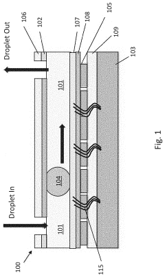
[0043]An example EWoD device was fabricated by forming a bottom plate with an active matrix of 10 nm thick molybdenum electrodes on a glass substrate, controlled by a commercial image driver chip (UltraChip). The electrodes were coated with a 100 nm stack of alumina, hafnium oxide and tantalum oxide dielectric layer topped with a 100 nm hydrophobic layer of Teflon® AF-1600 (Chemours, Wilmington Del.). A top plate featuring a transparent indium tin oxide (ITO) electrode was separated from the bottom plate with a 150 μm spacer, creating a microfluidic region that was filled with dodecane as carrier fluid. The driver chip was coupled to an exterior drive controller (E Ink Corporation Hulk controller) and a series of “images” were provided that resulted in the desired droplet actuation.

[0044]A droplet of an aqueous solution containing 0.05 wt % surfactant Tween® 20 (Croda, Edison, N.J.) was introduced in the microfluidic region and subjected to heating at 80° C. (hot plate—Fisher Scient...


PUM

PropertyMeasurementUnit
temperatureaaaaaaaaaa

Abstract

A method for degassing a microfluidic droplet by combining electrowetting and heating to induce formation of gaseous bubbles in the droplet. In an embodiment the methods are carried out on an active matrix of electrowetting electrodes including a hydrophobic coating. A carrier fluid is flowed against the droplet motion propelled by electrowetting to facilitate rapid removal of the gasses departing the droplet.

Description

RELATED APPLICATIONS[0001]This application claims priority to U.S. Provisional Patent Application No. 62 / 966,162, filed Jan. 27, 2020. All patents and publications disclosed herein are incorporated by reference in their entireties.BACKGROUND[0002]Microfluidics refers to the behavior, precise control, and manipulation of fluids that are geometrically constrained to a small scale (typically sub-millimeter) at which capillary penetration governs mass transport. It is a multidisciplinary field that involves engineering, physics, chemistry, biochemistry, nanotechnology, and biotechnology. It has practical applications in the design of systems that process low volumes of fluids to achieve multiplexing, automation, and high-throughput screening. Microfluidic structures include micropneumatic systems, i.e., microsystems for the handling of off-chip fluids (liquid pumps, gas valves, and the like), and digital microfluidic (DMF) devices for the on-chip handling of nanoliter (nl) and picoliter...

Claims


Application Information

Patent Timeline
Patent Type & Authority Applications(United States)
IPC IPC(8): G01N27/447B01D19/00B01L3/00
CPCG01N27/44704G01N27/44791B01L2300/18B01D19/0073B01L3/502715B01D19/0063B01L3/502792B01L2300/0645B01L2300/161B01L2300/1805B01L2400/0427B01L2200/0684B01L2200/0678B01L2300/0883B01L2200/0673
Inventor GUPTA, TANYASLOMINSKI, LUKE M.ZHITOMIRSKY, DAVIDPAOLINI, JR., RICHARD J.
Owner NUCLERA LTD