
Battery Pack Diagnosis Apparatus

Active Publication Date: 2021-07-29
LG ENERGY SOLUTION LTD
View PDF0 Cites 1 Cited by
  • Summary
  • Abstract
  • Description
  • Claims
  • Application Information

AI Technical Summary

Benefits of technology

The present patent aims to provide a method for effectively diagnosing the operation of a charging and discharging switching unit in a battery pack. This is achieved by using a simple circuit configuration with a single switching element and reducing the number of resistors needed for diagnosis. This simplifies the control configuration for the switching element and reduces diagnostic errors, allowing for quicker diagnosis and improved productivity.

Problems solved by technology

In addition, when overcurrent flows in the charging and discharging path, the fuse may be disconnected to irreversibly block the charging and discharging path.
If an abnormality occurs in the charging and discharging switch or the fuse not to properly permit or block the flow of the charging and discharging current, the battery pack may be damaged, and also a device or user connected to the battery pack may be seriously damaged.
Thus, if the flow of the charging and discharging current is not blocked in time, the battery pack may be damaged, and also the corresponding device may be damaged or ignited.
Thus, if the current is not properly turned on / off, the users may be injured along with material damage.
However, effective techniques for diagnosing the charging and discharging switching element have not been proposed.
For example, in the case of conventional diagnostic techniques, a circuit structure or a result calculation process is complicated, which however still have many problems such as difficulty in quick processing, many errors, requirement for a high-performance control device for accurate processing, an uneasy manufacturing process, or high manufacture cost.

Method used


Image

  • Battery Pack Diagnosis Apparatus
  • Battery Pack Diagnosis Apparatus
  • Battery Pack Diagnosis Apparatus

Examples


Embodiment Construction

[0046]Hereinafter, preferred embodiments of the present disclosure will be described in detail with reference to the accompanying drawings. Prior to the description, it should be understood that the terms used in the specification and the appended claims should not be construed as limited to general and dictionary meanings, but interpreted based on the meanings and concepts corresponding to technical aspects of the present disclosure on the basis of the principle that the inventor is allowed to define terms appropriately for the best explanation.

[0047]Therefore, the description proposed herein is just a preferable example for the purpose of illustrations only, not intended to limit the scope of the disclosure, so it should be understood that other equivalents and modifications could be made thereto without departing from the scope of the disclosure.

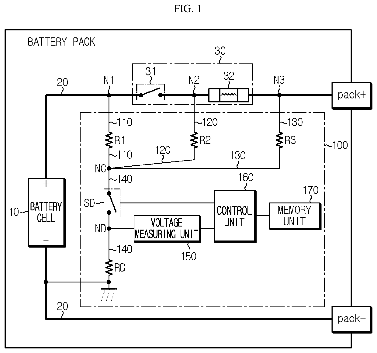
[0048]FIG. 1 is a diagram schematically showing a configuration in which a battery pack diagnosing apparatus according to an embodiment ...


PUM


Abstract

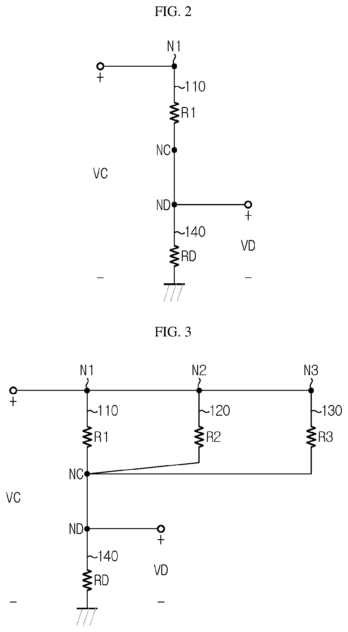
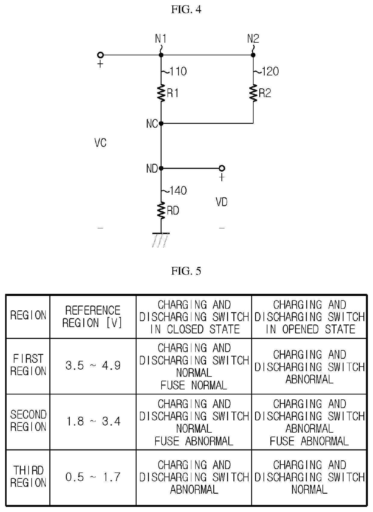
An apparatus and method for diagnosing whether a charging and discharging switching element provided on a charging and discharging path of a battery pack operates normally. A charging and discharging switching unit having a charging and discharging switch and a fuse is installed on a charging and discharging path between a battery cell and a pack terminal. The apparatus includes a first diagnosing path a second diagnosing path, a third diagnosing path, an integrated diagnosing path having a diagnosis switching unit and a diagnosis resistor, a voltage measuring unit, and a control unit configured to turn on and off the diagnosis switching unit and determine whether the charging and discharging switching unit is operating abnormally based on the diagnosis voltage measured by the voltage measuring unit.

Description

CROSS-REFERENCE TO RELATED APPLICATIONS[0001]The present application is a national phase entry under 35 U.S.C. § 371 of International Application No. PCT / KR2020 / 000546 filed Jan. 10, 2020, published in Korean, which claims priority from Korean Patent Application No. 10-2019-0004160 filed Jan. 11, 2019, all of which are incorporated herein by reference.TECHNICAL FIELD[0002]The present disclosure relates to a technique for diagnosing a battery pack, and more particularly, to a technique for diagnosing whether a charging and discharging switching element provided on a charging and discharging path of the battery pack operates normally.BACKGROUND ART[0003]Recently, as the demand for portable electronic products such as laptops, video cameras and portable telephones has rapidly increased and storage batteries for energy storage, robots, satellites, or the like have been developed in earnest, high-performance secondary batteries capable of being repeatedly charged and discharged are being...

Claims


Application Information

Patent Timeline
IPC IPC(8): G01R1/20G01R31/327G01R31/74H01M10/48H01M10/42G01R19/165H02J7/00
CPCG01R1/203G01R31/327G01R31/74H02J7/007H01M10/4207G01R19/16566H01M10/48Y02E60/10G01R31/3277G01R31/3278G01R19/16509G01R19/16519G01R19/16576H01M10/44H01M2010/4278H01M2010/4271H01M10/425Y02T10/70H02H7/18H02H3/087H02H3/046G01R19/16571G01R31/392G01R31/367B60L58/16
Inventor OCK, JANG-SOOPARK, YEON-DO
Owner LG ENERGY SOLUTION LTD
Features
  • Generate Ideas
  • Intellectual Property
  • Life Sciences
  • Materials
  • Tech Scout
  • Unparalleled Data Quality
  • Higher Quality Content
  • 60% Fewer Hallucinations
Learn More