Electrically-controlled optical device with a front shell

a front shell and optical device technology, applied in the direction of ion implantation coating, application, coating, etc., can solve the problems of optical element sharding, optical element pieces breaking away, damage to the eye of the wearer, etc., to prevent the front shell from fracturing or shattering, improve the impact resistance, and improve the overall thickness or weight

Pending Publication Date: 2021-08-12
ESSILOR INT CIE GEN DOPTIQUE
View PDF7 Cites 1 Cited by
  • Summary
  • Abstract
  • Description
  • Claims
  • Application Information

AI Technical Summary

Benefits of technology

[0013]Advantageously, the electrically-controlled optical device of the invention has an improved impact resistance due to the primer layer over known electrically-controlled optical devices, without the total thickness or weight being significantly increased.
[0014]Advantageously, the electrically-controlled optical device according to the invention is able to prevent the front shell to fracture or shatter when the front shell is submitted to the FDA drop ball test. In other words, the invention prevents pieces to be detached because the front shell does not break with this test and an impact energy of 200 mJ, thus protecting the eye of the user from being reached by any broken pieces of the front shell, thanks to the primer layer.

Problems solved by technology

When manufacturing a new optical element, it is necessary to take into account that in case of an accidental impact with sufficient force, the optical element may shatter.
As a consequence, pieces of the optical element may break away and damage the eye of the wearer.
However, some coatings are known to have a detrimental effect on resistance to impacts.
Limitations on the choice of materials arise from the nature of the function to be applied and from the conditions applied on the optical element during manufacturing and during use.

Method used


Image

  • Electrically-controlled optical device with a front shell
  • Electrically-controlled optical device with a front shell

Examples


Embodiment Construction

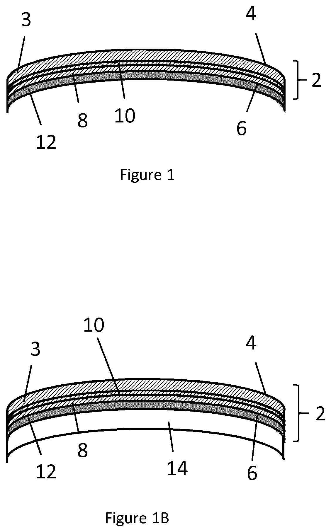
[0047]The invention relates to an electrically-controlled optical device intended to be placed before a user's eye, the electrically-controlled optical device being an ophthalmic device.

[0048]The invention relates to any kind of electrically-controlled optical device, including active lenses, virtual reality devices, augmented reality devices, LCD displays, e-focus lenses (know as lenses including an active focus or dynamic vision correction), active polarizing devices. The electrically-controlled optical device may comprise any optical element which may be included in eyewear, such as a solar lens, an electrochromic cell, a light guide, a holographic mirror. The electrically-controlled optical device may comprise a standard or a specific frame, such as an electronic frame.

[0049]In some embodiments, the electrically-controlled optical device is a head-mounted device, preferably a head-mounted display.

[0050]In some embodiments, the electrically-controlled optical device has a dioptri...


PUM

PropertyMeasurementUnit
impact energyaaaaaaaaaa
thickaaaaaaaaaa
thicknessaaaaaaaaaa

Abstract

An electrically-controlled optical device intended to be placed in front of a user's eye, the electrically-controlled optical device being an ophthalmic device, the electrically-controlled optical device comprising: a front shell defining a front surface and a back surface opposed to the front surface, the front shell comprising a slab, at least one functional layer arranged on the back surface and one primer layer, said primer layer being arranged between the at least one functional layer and the slab; and an electrically-controlled object facing the back surface of the front shell wherein the primer layer is conformed such that the electrically-controlled optical device is mechanically resistant to an impact energy of at least 200 mJ.

Description

FIELD OF THE INVENTION[0001]The invention relates to an electrically-controlled optical device.[0002]The invention further relates to a method for manufacturing an electrically-controlled optical device.BACKGROUND OF THE INVENTION[0003]When manufacturing a new optical element, it is necessary to take into account that in case of an accidental impact with sufficient force, the optical element may shatter. As a consequence, pieces of the optical element may break away and damage the eye of the wearer.[0004]The choice of material is important because it affects the weight and thickness of the optical element and its resistance to shocks. There are two main types of transparent materials used in optical devices: organic materials, like polycarbonate, and mineral glass, like BK7.[0005]In addition, eyewear having a specific function, such as an electrically-controlled optical device, may require applying a coating on a surface of an optical element. However, some coatings are known to hav...

Claims


Application Information

Patent Timeline
Patent Type & Authority Applications(United States)
IPC IPC(8): G02C7/10C23C14/34B29D11/00
CPCG02C7/101G02C2202/16B29D11/00038C23C14/34
Inventor GUILLOU, HÉLÈNEBIVER, CLAUDINEUHALTE NOGUES, SIRAESCAICH, DAVIDIMURA, MASAAKI
Owner ESSILOR INT CIE GEN DOPTIQUE
Why Eureka
Try Eureka