
Memory auxiliary heat transfer structure

a technology of auxiliary heat transfer and memory, which is applied in the direction of lighting and heating apparatus, instruments, and semiconductor/solid-state device details, etc., can solve the problems of difficult rework, inability for a common user to replace internal damaged electronic components such as memory units, and inability to meet the heat dissipation requirements of conventional heat dissipation means, etc., to achieve better wear resistance and thermo-conductivity, and increase the wear resistance of the chip

Pending Publication Date: 2021-08-12
ASIA VITAL COMPONENTS (CHINA) CO LTD
View PDF5 Cites 1 Cited by
  • Summary
  • Abstract
  • Description
  • Claims
  • Application Information

AI Technical Summary

Benefits of technology

The present invention provides a memory auxiliary heat transfer structure that improves the chip of the memory and the surface of the water-cooling assembly by increasing wear resistance and heat transfer coefficient, reducing heat resistance. Additionally, the strategy allows for better wear resistance and thermo-conductivity, enabling frequent replacement of the memory unit without damaging the water-cooling assembly and chip.

Problems solved by technology

Therefore, the conventional heat dissipation means can hardly satisfy the heat dissipation requirement and a water-cooling means must be employed to dissipate the heat.
Once the water-cooling set is assembled, it is quite hard to rework.
Therefore, it is impossible for a common user himself / herself to replace the internal damaged electronic component such as the memory unit.
This is quite inconvenient.
Moreover, due to the frequent insertion / extraction, the outer surface of the external case (metal or ceramic material) packaging the memory chip will contact and abrade the water-cooling set.
As a result, scrapes are often formed on the surface of the external case packaging the memory chip to cause heat resistance or damage the external case to expose the memory chip and contaminate the memory chip.
Furthermore, the surface of the pipeline of the water-cooling set is apt to abrade the external case packaging the memory chip so that the pipeline of the water-cooling set is easy to damage to cause leakage and short-circuit and burnout of the memory.
In both the assembling and reworking processes, the abrasion will cause the above problems to be improved.

Method used


Image

  • Memory auxiliary heat transfer structure
  • Memory auxiliary heat transfer structure
  • Memory auxiliary heat transfer structure

Examples


Embodiment Construction

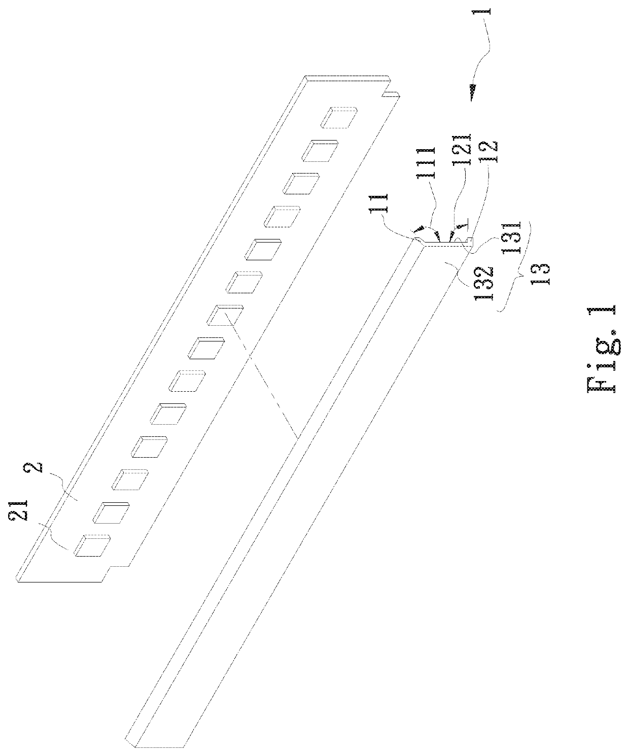
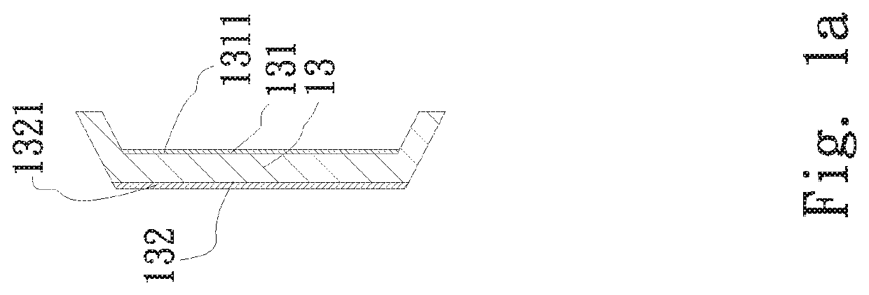
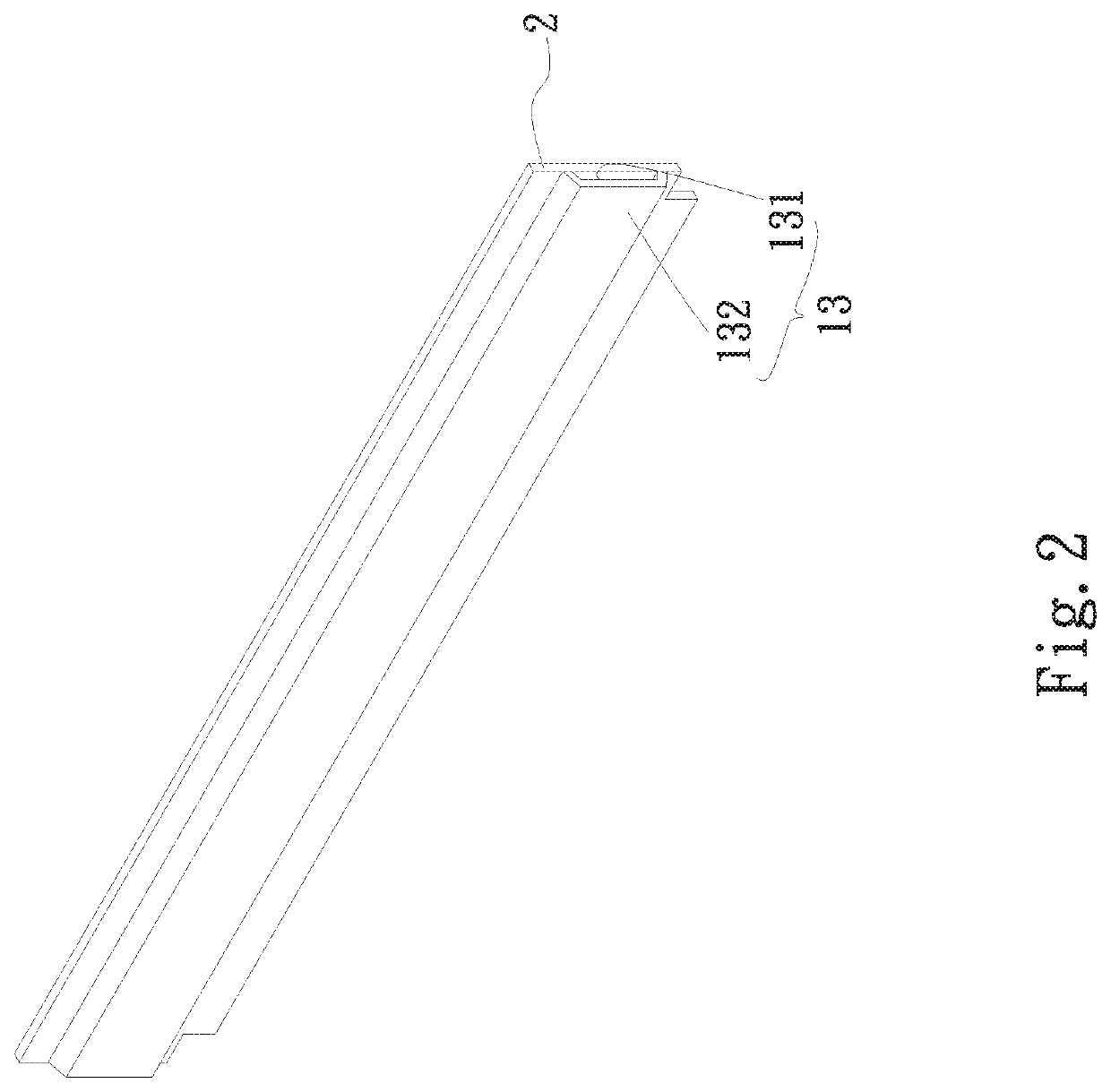
[0019]Please refer to FIGS. 1, 1a and 2. FIG. 1 is a perspective exploded view of a first embodiment of the memory auxiliary heat transfer structure of the present invention. FIG. 1a is a sectional view of the first embodiment of the memory auxiliary heat transfer structure of the present invention. FIG. 2 is a perspective assembled view of the first embodiment of the memory auxiliary heat transfer structure of the present invention. According to the first embodiment, the memory auxiliary heat transfer structure of the present invention is correspondingly assembled with at least one memory unit and a water-cooling assembly. The memory auxiliary heat transfer structure includes a main body 1.

[0020]The main body 1 has a first end 11, a second end 12 and a middle section 13. Two ends of the middle section 13 extend to connect with the first and second ends 11, 12. Angles are contained between the middle section 13 and the first and second ends 11, 12. Alternatively, a curved face or an...


PUM


Abstract

A memory auxiliary heat transfer structure is correspondingly assembled with at least one memory unit and a water-cooling assembly. The memory auxiliary heat transfer structure includes a main body. The main body has a first end, a second end and a middle section. The middle section has a heated side and a contact side. The heated side is disposed corresponding to at least one chip disposed on the memory unit. The contact side is attached to and assembled with the water-cooling assembly. The memory auxiliary heat transfer structure serves to reduce the friction between the memory unit and the water-cooling assembly and fill the gap so as to reduce the heat resistance.

Description

BACKGROUND OF THE INVENTION1. Field of the Invention[0001]The present invention relates generally to a memory auxiliary heat transfer structure, and more particularly to a memory auxiliary heat transfer structure, which has wear resistance and high heat transfer coefficient to reduce the heat resistance.2. Description of the Related Art[0002]The current electronic apparatuses have many electronic chips inside for calculating data. These electronic chips are exactly the heat generation components in the electronic apparatus. In general, to dissipate the heat generated by the heat generation components, a conventional heat transfer component (heat pipe, vapor chamber, heat sink, etc.) is used to directly contact the heat source and a cooling fan is correspondingly disposed to forcedly dissipate the heat of the heat transfer component. However, with the advance of the electronic chips with stronger and stronger calculation capability, the heat generated by the electronic chips is also ...

Claims


Application Information

Patent Timeline
IPC IPC(8): H05K7/20G06F1/20H01L23/433F28F13/00
CPCH05K7/20272G06F1/20F28F2013/005F28F13/00H01L23/433G06F2200/201H01L23/473F28D1/03F28D2021/0029
Inventor LEE, SUNG-WEI
Owner ASIA VITAL COMPONENTS (CHINA) CO LTD
Learn More