
Eureka
For R&D, Eureka makes reading and utilizing patents & technical documents easy.
Eureka AIR
Designed for self-driven R&D workflows. Generate viable solutions, solve complex R&D challenges, empower your innovation with AI.

Eureka Materials
Designed for material experts only. Revolutionize your material R&D, from search, analyze, to developing new materials.

TechResearch
Generate reliable direction feasibility study reports for your R&D in just a few steps.

TechSeek
Discover and master advanced knowledge NOW. Basics, ideas, possibilities, all at once.

TechMind
As an expert in R&D Theories, TechMind can generates customized viable solutions instantly.

TechRisk
Analyze your overall solution with one click, know your potential R&D risks in advance.

TechMonitor
Get weekly tech updates, stay abreast of the latest tech innovations and key insights.
Thermal imaging camera device
- Summary
- Abstract
- Description
- Claims
- Application Information
AI Technical Summary
Benefits of technology
Problems solved by technology
Method used
Image

Examples
example method
For Controlling Multiple Camera Systems
[0159]FIG. 9 illustrates a flowchart of an example method 900 for generating thermal image data and for transmitting the thermal image data to any number of external computing devices. Here, however, method 900 may be performed by a single uncooled thermal imaging sensor, or, alternatively, it may be performed by a combination or group of multiple uncooled thermal imaging sensors.
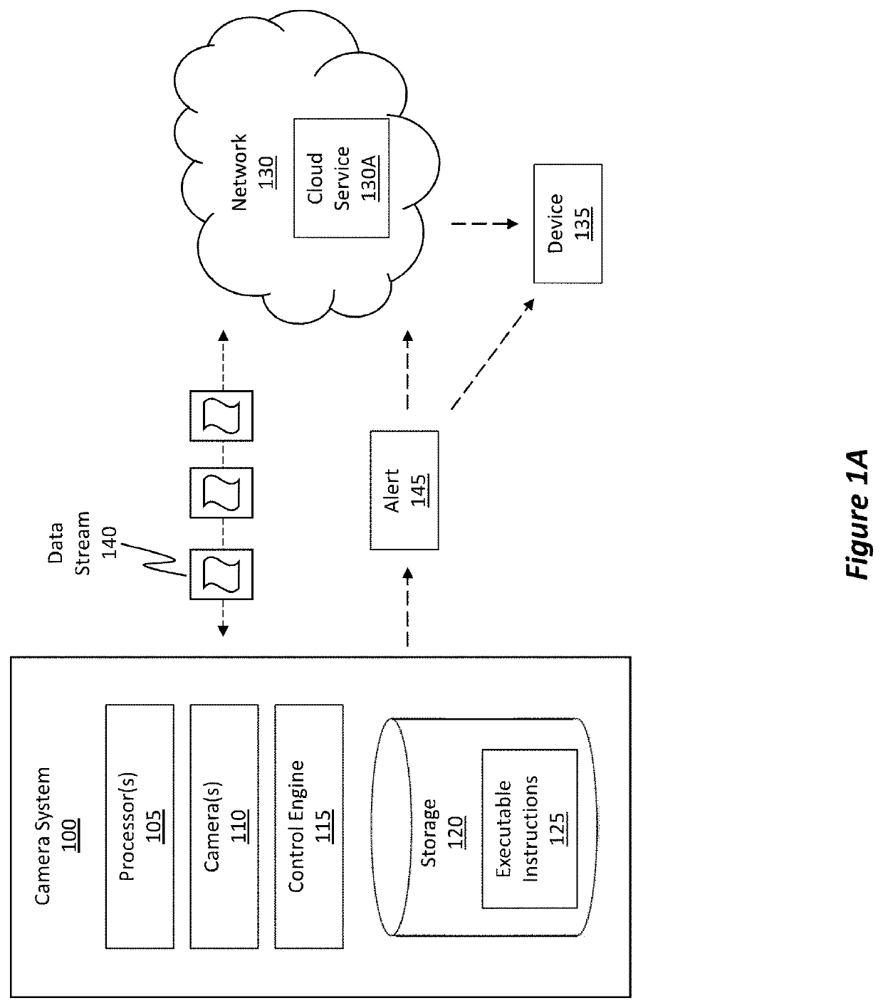
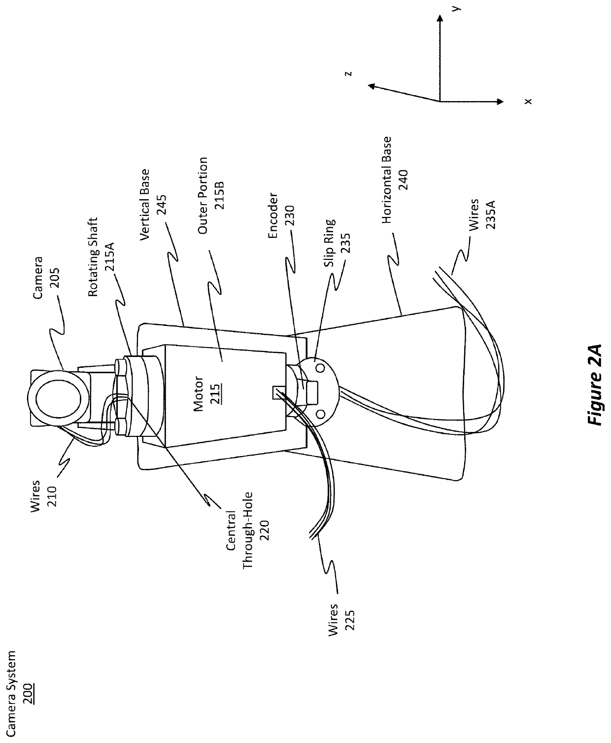
[0160]Initially, for each uncooled thermal imaging sensor included in a group of one or more uncooled thermal imaging sensor(s), method 900 includes performing (act 905) the two acts / operations listed in the dotted box shown in FIG. 9. Method 900 may be performed by a camera system (e.g., camera system 200 of FIG. 2A) having a single uncooled thermal imaging sensor, or it may be performed by a group of uncooled thermal imaging sensors, as shown in FIG. 5B.
[0161]One act (act 910) includes controlling a corresponding movement of each one of the uncooled thermal imaging s...
example use-case
Scenarios
[0167]FIG. 10 illustrates a flowchart of an example method 1000 for generating thermal image data in one or more specific use case scenarios. The specific use case scenarios are described in more detail with respect to FIGS. 11-17. FIG. 10, on the other hand, simply references the scenarios in a generalized manner.
[0168]Initially, method 1000 includes an act (act 1005) of placing a rotating camera system in an environment to monitor a determined set of conditions. Here, this rotating camera system is configured in the manner described earlier.
[0169]Once the rotating camera system is positioned within the environment, there is an act (act 1010) of activating the rotating camera system within the environment to cause the rotating camera system to begin monitoring the environment. Such activation may include turning the rotating camera system on or triggering the system to wake up in some manner.
[0170]Then, there is an act (act 1015) of using the activated rotating camera syst...
PUM
 Abstract
Description
Claims
Application Information
 - R&D Engineer
- R&D Manager
- IP Professional
- Industry Leading Data Capabilities
- Powerful AI technology
- Patent DNA Extraction
Browse by: Latest US Patents, China's latest patents, Technical Efficacy Thesaurus, Application Domain, Technology Topic, Popular Technical Reports.
© 2024 PatSnap. All rights reserved.Legal|Privacy policy|Modern Slavery Act Transparency Statement|Sitemap|About US| Contact US: help@patsnap.com