Light and Shadow Guided Needle Positioning System and Method

a positioning system and shadow technology, applied in the field of interventional medicine, can solve problems such as discomfort for patients, unresolved problems, and exposing tissue to hazardous radiation levels

Active Publication Date: 2021-09-23
KORNERSTONE DEVICES PVT LTD
View PDF12 Cites 1 Cited by
  • Summary
  • Abstract
  • Description
  • Claims
  • Application Information

AI Technical Summary

Benefits of technology

[0011]Another object of the present invention is to provide a system and method for accurately positioning a needle towards a target point from a point of insertion on a patient's body without making any direct contact with the patient's body.
[0040]According to one embodiment of the present invention, a method is provided for precise positioning of a needle using a light and shadow. The method involves receiving and displaying plurality of DICOM images, selecting a point of insertion of the needle on the patient's body and a target point inside the patient's body, computing needle coordinates and assist in aligning the needle using combination of shadow of the needle and laser cross-hair.

Problems solved by technology

A common issue in conducting the core biopsies is in the identification of an exact location of a lesion and thereafter the accurate guiding of the biopsy needle to that lesion.
Such methods and apparatus still pose several issues and do not solve the problems entirely.
For example, many such solutions are invasive and cause discomfort to the patient.
A common drawback of the existing systems is the need for multiple X-ray images of the lesion, thereby exposing the tissue to hazardous levels of radiation.
These systems also do not provide a real-time imaging of the needle trajectory as the needle is inserted into the body.
Most of the times, as the biopsy needle is secured in a fixed device and these systems do not provide a freedom of movement for the needle relative to the target tissue.
Thus, the conventional systems and methods for collection of a biopsy sample are complicated, cumbersome, and overlay invasively to the patient.
Further, the use of such equipment is expensive, time consuming, and unjustified in small practices.

Method used


Image

  • Light and Shadow Guided Needle Positioning System and Method
  • Light and Shadow Guided Needle Positioning System and Method
  • Light and Shadow Guided Needle Positioning System and Method

Examples


Embodiment Construction

[0056]In the following detailed description, reference is made to the accompanying drawings that form a part hereof, and in which the specific embodiments that may be practiced is shown by way of illustration. These embodiments are described in sufficient detail to enable those skilled in the art to practice the embodiments and it is to be understood that the logical, mechanical and other changes may be made without departing from the scope of the embodiments. The following detailed description is therefore not to be taken in a limiting sense.

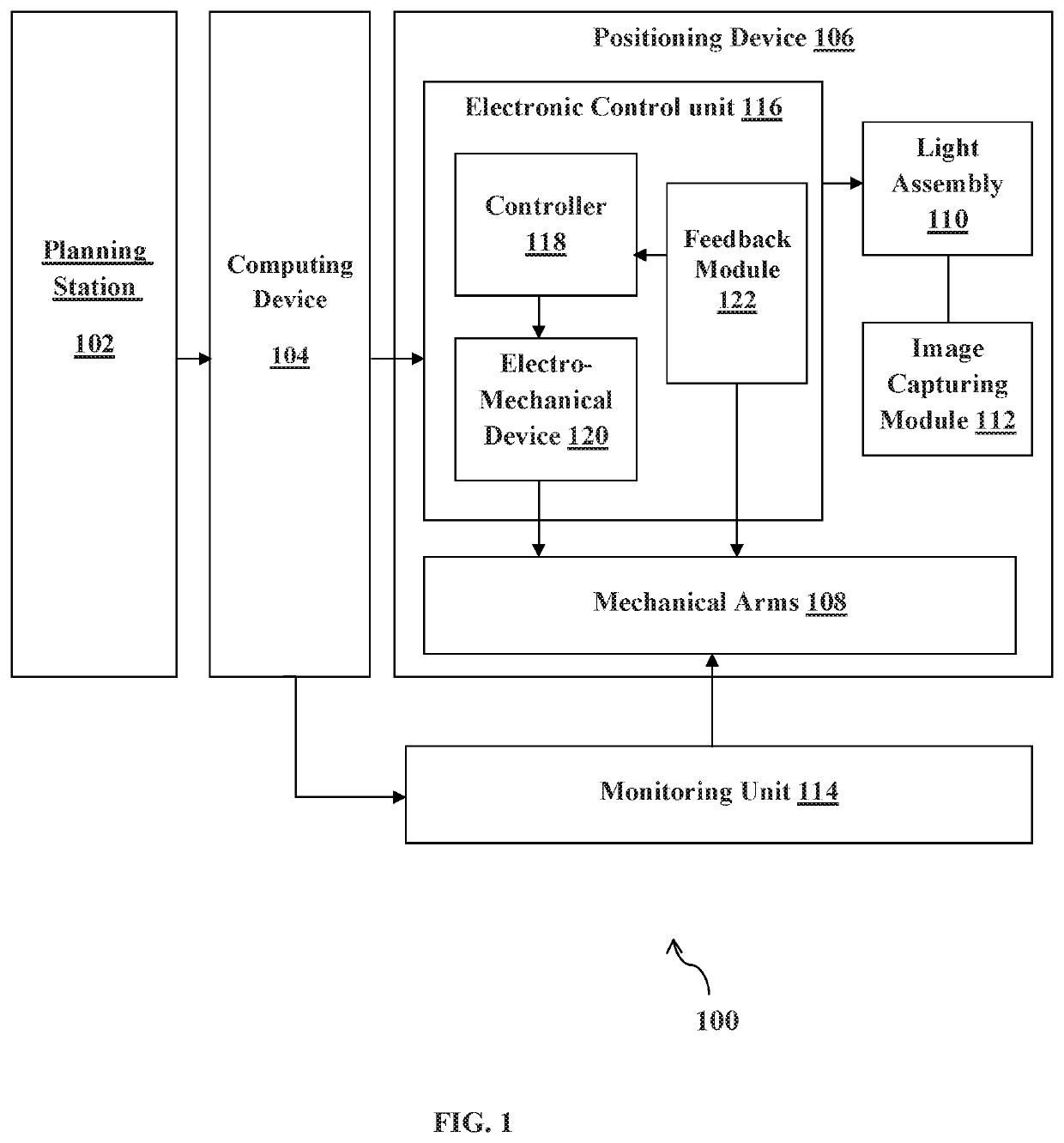
[0057]The various embodiments of the present invention provide a system for positioning a needle based on light and shadow. The system comprises a planning station for receiving and displaying a Digital Imaging and Communications in Medicine (DICOM) images of a patient from an imaging device in order to select a point of insertion of a needle on the patient's body and a target point inside the patient's body. A computing device is configured fo...


PUM


Abstract

The embodiments of the present invention provide a system and method for light and shadow guided needle positioning. DICOM images of a patient are captured for identifying a point of insertion of a needle on the patient's body and a target point inside the patient's body. Needle coordinates are computed based on the captured DICOM images to position the mechanical arms. Light is projected at a particular angle on the needle to form shadows of the needle. Laser light beams are projected to form cross hair at the point of insertion. Images or videos of the point of insertion, shadow of the needle and the cross hair are captured and displayed on a monitoring unit. A virtual circle is projected on the displayed image and is aligned with the point of insertion, shadow of the needle and cross hair in order to insert the needle precisely.

Description

TECHNICAL FIELD[0001]The present invention is generally related to interventional medicine. The present invention is particularly related to needle positioning systems and methods for conducting medical procedure. The present invention is more particularly related to a system and method for guiding and positioning the needle towards a target point from a point of insertion on patient's body using shadows of the needle and light.BACKGROUND OF THE INVENTION[0002]In the field of interventional medicine, a medical procedure is performed for diagnostic or treatment purposes by taking a sample from a patient's body. For example, a sample tissue of a specific internal organ from the patient's body is collected by inserting a medical device such as a needle. As an insertion of the needle at correct angle and to a right depth is critical, the needle needs to be guided into a desired location within the body using various imaging and positioning techniques. These positioning techniques are ty...

Claims


Application Information

Patent Timeline
Patent Type & Authority Applications(United States)
IPC IPC(8): A61B90/13A61B34/10
CPCA61B90/13A61B2034/107A61B34/10A61B6/032A61B90/11A61B2090/365A61B34/00
Inventor ROY, SANTOSHAMRAJENDRAN, CHERUKANDATH
Owner KORNERSTONE DEVICES PVT LTD
Why Eureka
Try Eureka