Torque vectoring device
a torque vectoring and torque technology, applied in the direction of electric propulsion mounting, gearing details, gearing, etc., can solve the problems of difficult structure of reversing motor, complicated structure of drive gear unit, etc., and achieve the effect of simple uniaxial structure, reduced torque vectoring device size, and easy arrangemen
- Summary
- Abstract
- Description
- Claims
- Application Information
AI Technical Summary
Benefits of technology
Problems solved by technology
Method used
Image
Examples
first example
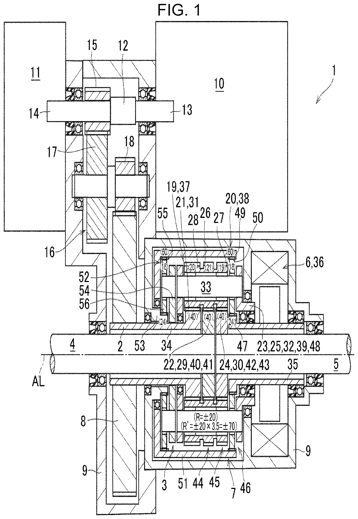
[0035]Referring now to FIG. 1, there is shown a structure of a torque vectoring device 1 according to the first example of the present disclosure. As shown in FIG. 1, the torque vectoring device 1 comprises an input member 2, a differential mechanism 3, a first rotary shaft 4, a second rotary shaft 5, an actuator 6, and a reversing mechanism 7.
[0036]A torque generated by a prime mover is applied to the input member 2 as a hollow rotary shaft. According to the first example, both ends of the input member 2 are supported by a case 9 of the torque vectoring device 1 in a rotatable manner. Specifically, the input member 2 is fitted onto the first rotary shaft 4 while being allowed to rotate relatively with first rotary shaft 4, and an input gear 8 is fitted onto the input member 2 to rotate integrally with the input gear 8. The input gear 8 is connected to a prime mover through a reduction gear train 16.
[0037]According to the first example, the prime mover includes a motor 10 and a brak...
second example
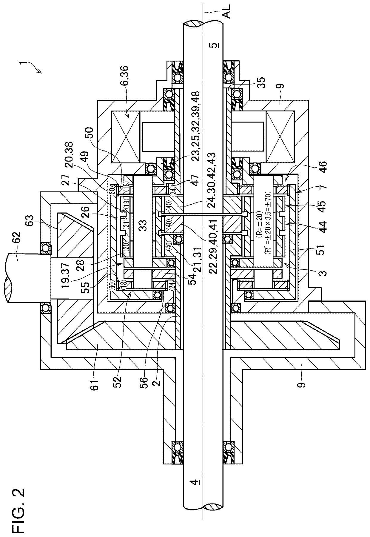
[0087]Turning to FIG. 2, there is shown the second example of the torque vectoring device 1 according to the present disclosure. The torque vectoring device 1 shown in FIG. 2 is designed to be arranged in the lateral direction of the vehicle. To this end, in the torque vectoring device 1 shown in FIG. 2, the first rotary shaft 4 and the second rotary shaft 5 extend coaxially in the lateral direction of the vehicle (i.e., along the rotational center axis AL shown in FIG. 2).
[0088]In the torque vectoring device 1 shown in FIG. 2, an input gear 61 is fitted onto the input member 2 to be rotated integrally with the input member 2. Specifically, the input gear 61 is a diametrically larger bevel gear, and is engaged with a diametrically smaller bevel gear 63 fitted onto a leading end (i.e., a lower end in FIG. 2) of a propeller shaft 62.
[0089]Specifically, the propeller shaft 62 extends perpendicular to the rotational center axis AL. The diametrically smaller bevel gear 63 is mounted on o...
third example
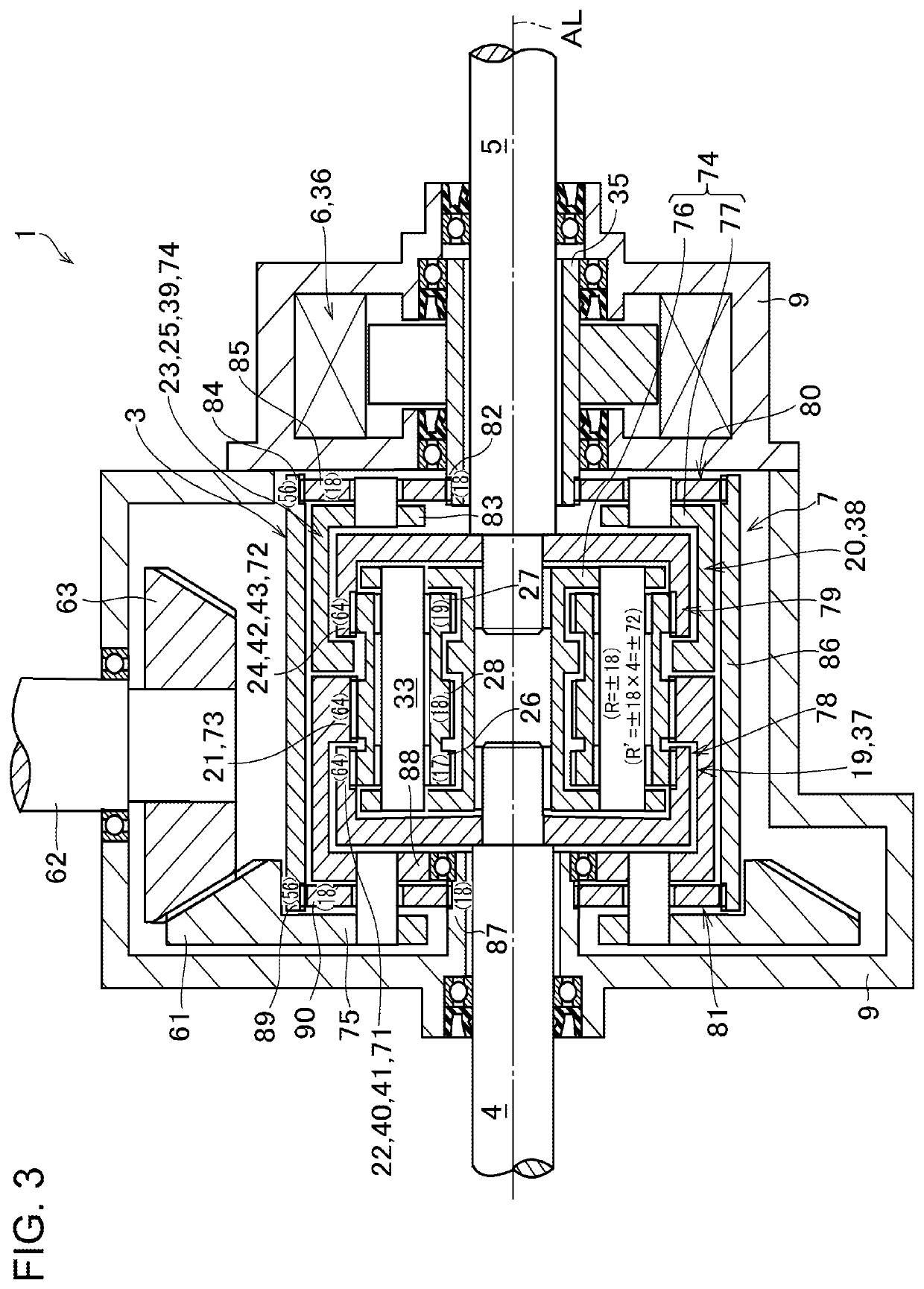
[0091]Turning to FIG. 3, there is shown the third example of the torque vectoring device 1 according to the present disclosure. According to the third example, the differential mechanism 3 comprises: the set of the first planetary gears 26, the set of the second planetary gears 27, and the set of the third planetary gears 28; a first ring gear 71, a second ring gear 72, and a third ring gear 73; and a carrier 74. The first planetary gear 26, the second planetary gear 27, and the third planetary gear 28 are formed integrally and coaxially on the planetary pinion, and the third planetary gear 28 is situated between the first planetary gear 26 and the second planetary gear 27. The first ring gear 71, the second ring gear 72, and the third ring gear 73 are also arranged coaxially to one another while being allowed to rotate relatively to one another, and the third ring gear 73 is situated between the first ring gear 71 and the second ring gear 72. Specifically, the first ring gear 71 en...
PUM
 Abstract
Description
Claims
Application Information
 - R&D
- Intellectual Property
- Life Sciences
- Materials
- Tech Scout
- Unparalleled Data Quality
- Higher Quality Content
- 60% Fewer Hallucinations
Browse by: Latest US Patents, China's latest patents, Technical Efficacy Thesaurus, Application Domain, Technology Topic, Popular Technical Reports.
© 2025 PatSnap. All rights reserved.Legal|Privacy policy|Modern Slavery Act Transparency Statement|Sitemap|About US| Contact US: help@patsnap.com


