Power supply network and hybrid vehicle

a power supply network and hybrid technology, applied in the direction of machines/engines, exhaust treatment electric control, transportation and packaging, etc., can solve the problems of not allowing the combustion engine itself, the catalyst may still be too cold to provide optimal performance, and the ehcs up to now cannot be used in hybrid electric vehicles easily, so as to achieve the effect of easy integration

Pending Publication Date: 2021-10-07
VITESCO TECH GERMANY GMBH
View PDF0 Cites 3 Cited by
  • Summary
  • Abstract
  • Description
  • Claims
  • Application Information

AI Technical Summary

Benefits of technology

[0008]This has the effect that a single power supply network is used in the vehicle to power electrical loads having supply voltage demands different from each other. It is in other words not necessary to provide several independent power supply networks, each for example having a battery providing an individual supply voltage different from each other. Furthermore, it is, for example, not necessary anymore to abstain from low-voltage applications in hybrid electric vehicles as they now may be powered from the usually already provided high-voltage power supply network. Thus, the power supply network allows a more environmental-friendly operation.
[0009]In an embodiment, the power supply network includes a converter arrangement arranged to convert the first supply voltage to the second supply voltage. The converter arrangement is in one embodiment operationally connected to the power supply network. Having a converter arrangement allows to downconvert the first supply voltage to the second supply voltage which is smaller than the first supply voltage in an easy manner so as to power the electric load which is configured to be powered with the second supply voltage from the power supply network.
[0011]In an embodiment, the primary transformer winding is part of the first power subnet and the at least one secondary transformer winding is part of the second power subnet. In an embodiment, the primary transformer winding is arranged side-by-side with the at least one secondary transformer winding in order to convert the first supply voltage to the second supply voltage via a magnetic field established between the primary transformer winding and the at least one secondary transformer winding. Inverters are well-known from other electronic applications and may thus easily be integrated into the present solution.
[0014]In an embodiment, the power supply network is a capacitor. The capacitor is arranged to be charged from the first power subnet. In an embodiment, the capacitor is arranged to provide the second supply voltage to the second power subnet. The capacitor is arranged in the second power subnet. In an embodiment, the capacitor is a super capacitor. In an embodiment, a subnet switch is arranged in the second power subnet to open and close a circuit forming the second power subnet. When the circuit is closed, a current provided by the capacitor may flow through the second power subnet so as to power the electrical loads connected thereto. When on the other hand the circuit is open, the capacitor will be charged. This allows, for example, to provide the second supply voltage for a short time period. The subnet switch itself may be supplied from the extra secondary transformer winding of a transformer, for example provided by the inverter.
[0018]This has the effect that a single power supply network may be used in the vehicle to power electrical loads having supply voltage demands different from each other. It is in other words not necessary to provide several independent power supply networks, each for example having a battery providing an individual supply voltage different from each other. Furthermore, it is, for example, not necessary anymore to abstain from low-voltage applications in hybrid electric vehicles as they now may be powered from the usually already provided high-voltage power supply network. Thus, the power supply network allows a more environmental-friendly operation.
[0019]In an embodiment, the power supply network is a first power subnet arranged to provide the first supply voltage and a second power subnet arranged to provide the second supply voltage. In an embodiment, the first power subnet and the second power subnet are operationally connected to each other via a converter arrangement. The converter arrangement in an embodiment includes an inverter so as to convert the first supply voltage to the second supply voltage. The inverter may be one or more transformer windings. In an embodiment, the inverter has one primary transformer winding to receive the first supply voltage and at least one secondary transformer winding to provide the second supply voltage downconverted from the first supply voltage. In an embodiment, the power supply network includes a high-voltage battery electrically connected to the first power subnet. The inverter is thus arranged to convert the first, comparably higher, supply voltage provided by the high-voltage battery to the first power subnet into the second, comparably smaller, supply voltage and to provide the second supply voltage to the second power subnet. Inverters are well-known from other electronic applications and may thus easily be integrated in the present solution.

Problems solved by technology

Thus, within a certain time period after a cold start of the combustion engine, the catalyst may still be too cold to provide optimum performance.
The combustion engine of a hybrid electric vehicle (HEV) will normally be switched on and off frequently during driving which may not allow the combustion engine itself to heat up an exhaust system and the catalyst to optimum performance.
However, EHCs up to now cannot be employed in hybrid electric vehicles easily as known power supply networks installed in hybrid electric vehicles usually provide a supply voltage of about 350 VDC while a EHC typically needs to be powered with between 10 VDC to 50 VDC, for example 12 VDC or 48 VDC.

Method used


Image

  • Power supply network and hybrid vehicle
  • Power supply network and hybrid vehicle

Examples


first embodiment

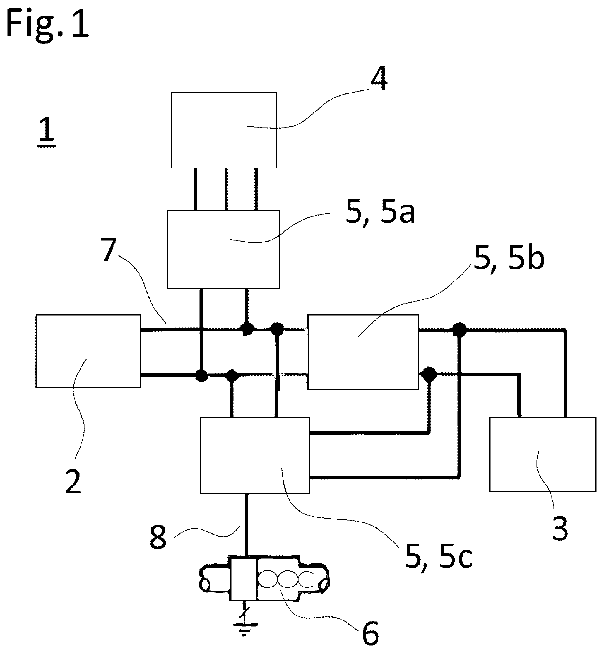
[0029]FIG. 1 schematically shows the power supply network 1 according to the invention. The power supply network 1 is installed in a hybrid electric vehicle. Many details of the hybrid electric vehicle are omitted so as to simplify the description. The power supply network 1 includes a high-voltage battery 2 providing 350 VDC, a low-voltage battery 3, and an electric machine 4. Furthermore, the power supply network 1 includes a converter arrangement 5a, 5b, 5c which includes an AC / DC-inverter 5a for powering the electric machine 4, a DC / DC-converter 5b for powering a vacuum pump (not shown) and a power steering (not shown), and an inverter 5c for powering an electrically heated catalyst (EHC) 6. A wiring between the components follows schematically from FIG. 1. Details about the inverter 5c for powering the EHC 6 are disclosed with more detail below referring to FIG. 2.

[0030]As shown, the power supply network 1 is arranged to provide a first supply voltage, from the 350 VDC high-vol...

second embodiment

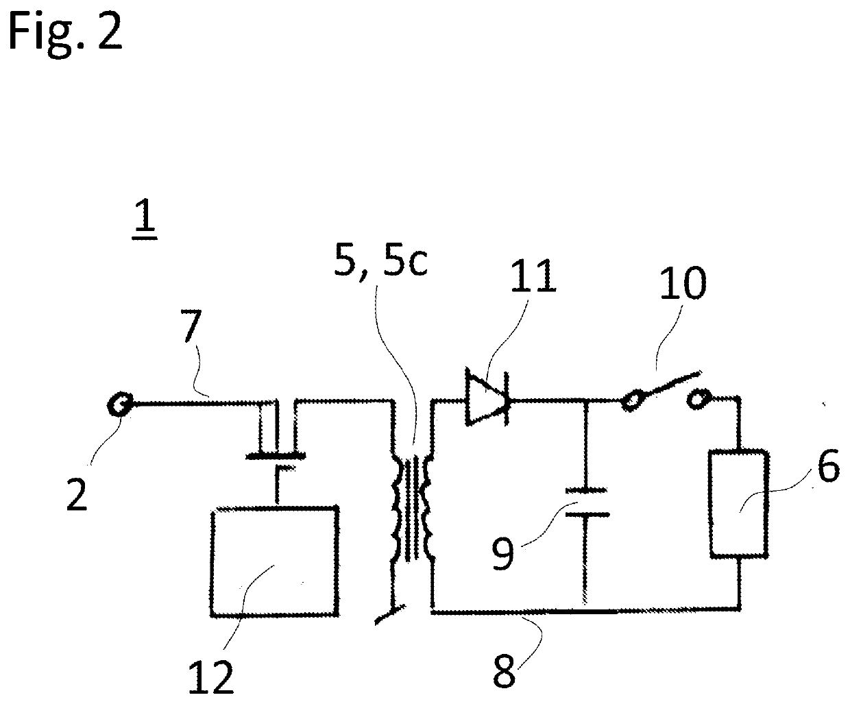
[0034]FIG. 2 schematically shows the power supply network 1 according to the invention. The power supply network 1 again is installed in a hybrid electric vehicle. The power supply network 1 here includes a capacitor 9. The capacitor 9 is arranged to be charged from the first power subnet 7, namely by the high-voltage battery 2, and is arranged to provide the second supply voltage to the second power subnet 8. To achieve this, the inverter 5c is configured to step down the 350 VDC provided by the high-voltage battery 2 to, in this case, 48 VDC supply voltage for the EHC 6. The wiring of the components follows from FIG. 2.

[0035]As may be seen from FIG. 2, the inverter 5c includes, as well as in the first embodiment shown in FIG. 1, a primary transformer winding which is part of the first power subnet 7 and a secondary transformer winding which is part of the second power subnet 8. As the inverter 5c thus operationally connects the first power subnet 7 to the second power subnet 8 whi...


PUM


Abstract

A power supply network for installation in a vehicle, wherein the power supply network is arranged to provide a first supply voltage so as to power electrical loads electrically connected to the power supply network with the first supply voltage. The power supply network is arranged to power an electric load which is configured to be powered with a second supply voltage smaller than the first supply voltage. A vehicle includes the power supply network operationally connected to the vehicle. The power supply network allows a more environmental-friendly operation.

Description

CROSS-REFERENCE TO RELATED APPLICATIONS[0001]This application claims priority to PCT Application PCT / EP2019 / 085560, filed Dec. 17, 2019, which claims priority to European Patent Application No. EP 18214506.0, filed Dec. 20, 2018. The disclosures of the above applications are incorporated herein by reference.FIELD OF THE INVENTION[0002]The present invention relates to a power supply network for installation in a vehicle, wherein the power supply network is arranged to provide a first supply voltage so as to power electrical loads electrically connected to the power supply network with the first supply voltage. The present invention furthermore relates to a hybrid vehicle, the vehicle including such a power supply network operationally connected to the vehicle.BACKGROUND OF THE INVENTION[0003]Legislation for combusting engines in vehicles is getting more and more strict. Exhaust gas provided by the combustion engine has to be cleaned via catalysts as much as possible before entering t...

Claims


Application Information

Patent Timeline
Patent Type & Authority Applications(United States)
IPC IPC(8): B60W20/16B60L1/02F01N3/20
CPCB60W20/16B60L1/02F01N3/2026B60L2210/40B60Y2200/92B60L2210/10B60Y2300/474F01N9/00F01N2590/11Y02A50/20Y02T10/12Y02T10/40B60W2530/12
Inventor FREDERIKSEN, FINNHANSEN, THOMAS-TARPBERTELSEN, BRIAN SKJOLD
Owner VITESCO TECH GERMANY GMBH
Why Eureka
Try Eureka