Process fluid lubricated pump

Pending Publication Date: 2021-10-21
SULZER MANAGEMENT AG
View PDF0 Cites 2 Cited by
  • Summary
  • Abstract
  • Description
  • Claims
  • Application Information

AI Technical Summary

Benefits of technology

The patent describes the use of water injection pumps for subsea applications, which require high pressure and little variation in speed. To achieve this, centrifugal pumps are used with liquid-filled or flooded induction motors or permanent magnet motors. Reliability and minimization of wear and degradation within the pump are important for subsea installations. The center bush supports the rotordynamic stability by providing stiffness and damping for rotor vibrations. The rotor is the entity of the rotating parts of the pump unit.

Problems solved by technology

Needless to say that the design of such pumps is challenging, in particular because these pumps shall operate in a difficult subsea environment for a long time period with as little as possible maintenance and service work.
Radial bearings, which are also designated as journal bearings, are complex, highly expensive components of a pump.
Thus, reducing the number of radial bearings for the pump shaft, reduces the complexity of the pump as well as the likelihood of a failure of the pump.
This has an impact on material cost as well as installation costs.
Although such mechanical seals are widely spread within the technology of centrifugal pumps they are somewhat problematic for subsea applications because they are quite complicated and usually require additional equipment, which is often considered as a drawback for subsea applications.
Without any additional measure this pressure would result in a very high flow of process fluid through the drive unit, which also would considerably reduce the efficiency of the pump.

Method used


Image

  • Process fluid lubricated pump
  • Process fluid lubricated pump
  • Process fluid lubricated pump

Examples


first embodiment

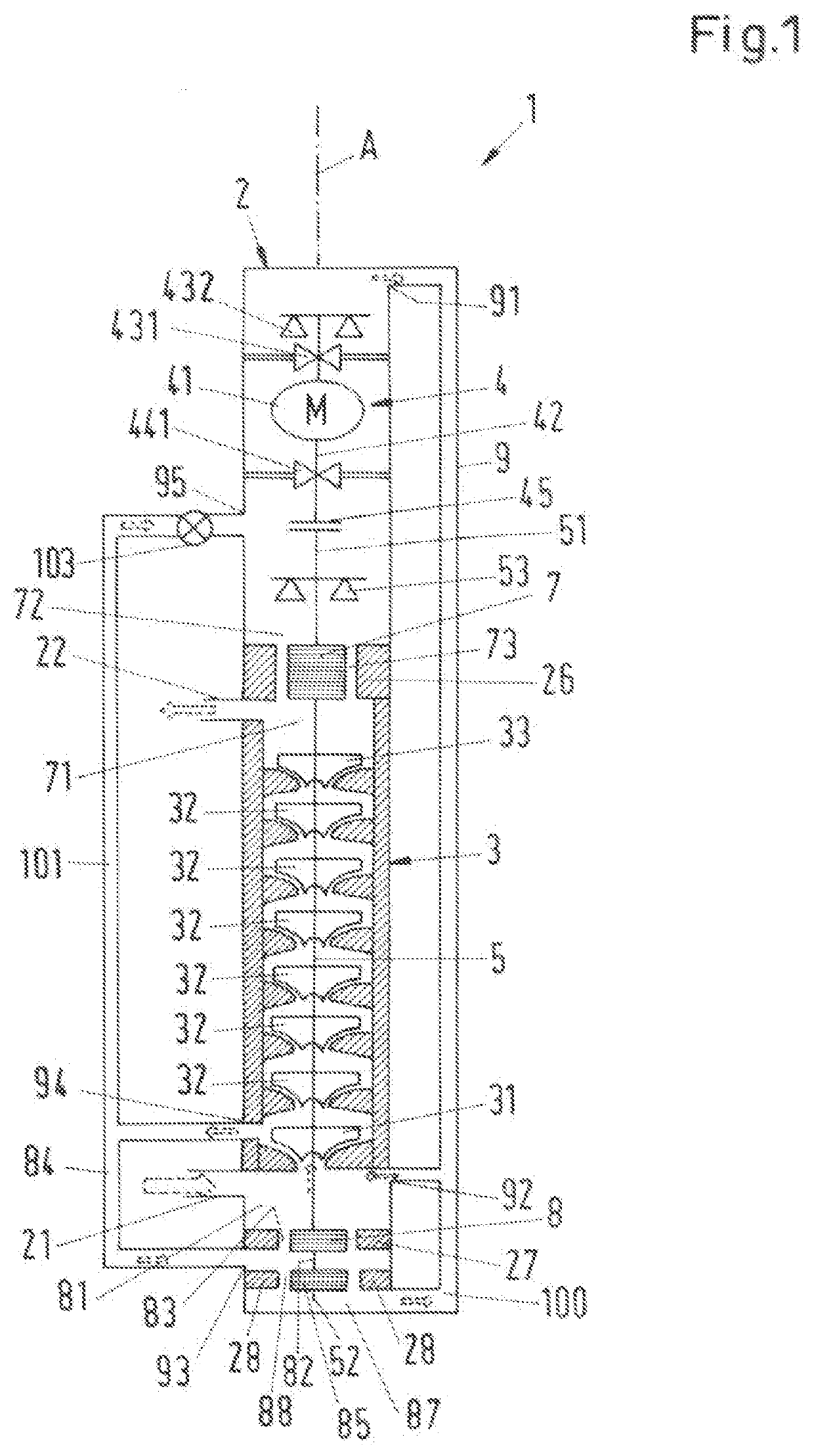
[0049]FIG. 1 shows a schematic cross-sectional view of a process fluid lubricated pump according to the invention, which is designated in its entity with reference numeral 1. The pump 1 is designed as a centrifugal pump for conveying a process fluid and has a common housing 2, a pump unit 3 and a drive unit 4. Both the pump unit 3 and the drive unit 4 are arranged within the common housing 2. The common housing 2 is designed as a pressure housing, which is able to withstand the pressure generated by the pump 1 as well as the pressure exerted on the pump 1 by the environment. The common housing 2 can comprise several housing parts, e.g. a pump housing and a drive housing, which are connected to each other to form the common housing 2 surrounding the pump unit 3 and the drive unit 4. It is also possible that a pump housing and a drive housing are inserted into a barrel housing which forms the common housing 2 of the pump 1.

[0050]In the following description reference is made by way of...

second embodiment

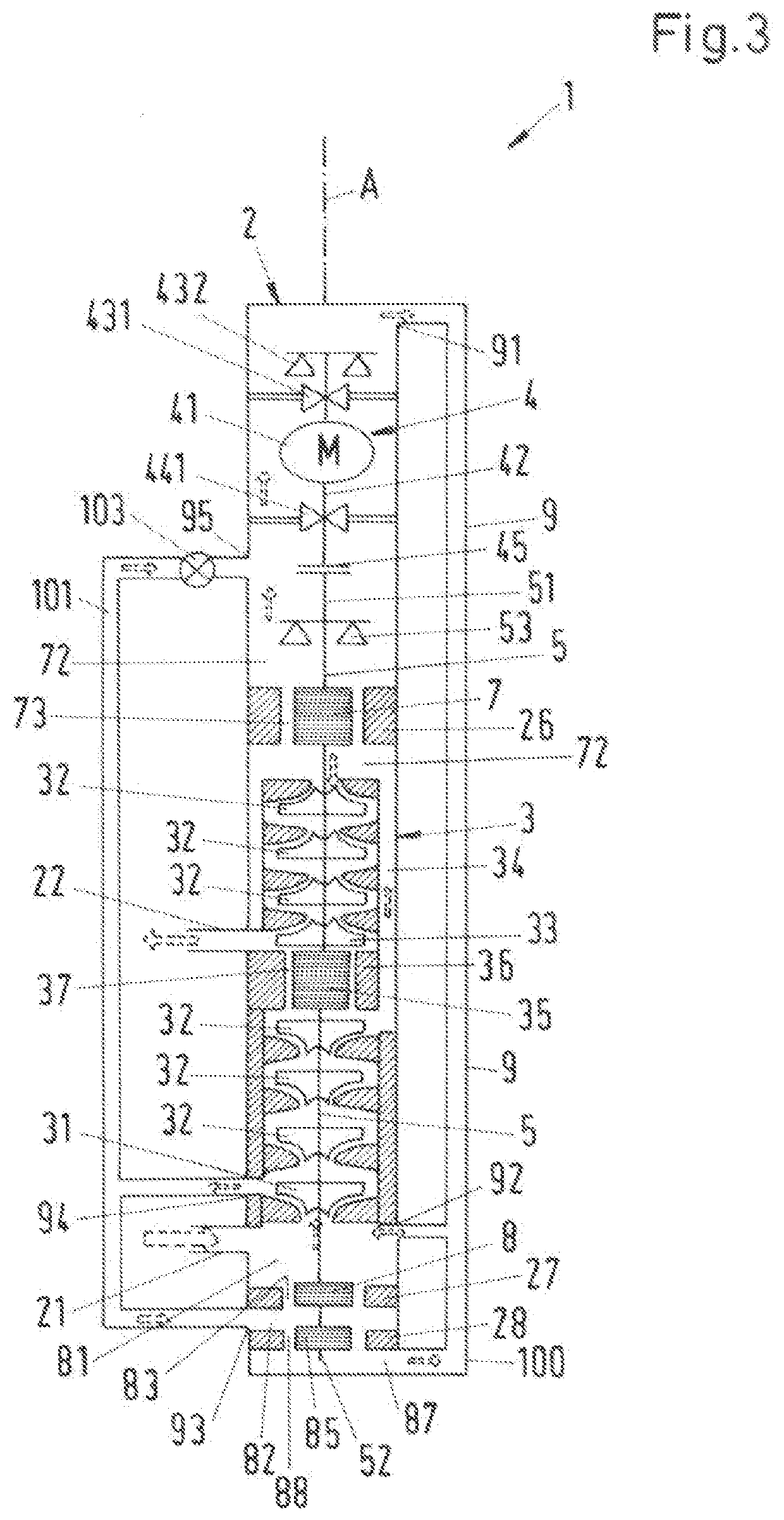
[0098]FIG. 3 shows a schematic cross-sectional view of a process fluid lubricated pump 1 according to the invention.

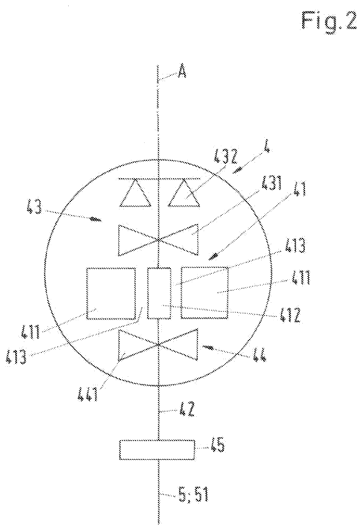
[0099]In the following description of the second embodiment of the process fluid lubricated pump 1 only the differences to the first embodiment are explained in more detail. The explanations with respect to the first embodiment are also valid in the same way or in analogously the same way for the second embodiment. Same reference numerals designate the same features that have been explained with reference to the first embodiment or functionally equivalent features. In particular, the drive unit explained with reference to FIG. 2 can also be used for the second embodiment.

[0100]Compared to the first embodiment, it is the main difference, that in the second embodiment of the pump 1 the impellers 31, 32, 33 are arranged in a back-to-back arrangement. The pump unit 3 comprises a first set of impellers 31, 32 and a second set of impellers 32, 33, wherein the first set of im...

third embodiment

[0107]FIG. 4 shows a schematic cross-sectional view of a process fluid lubricated pump 1 according to the invention.

[0108]In the following description of the third embodiment of the process fluid lubricated pump 1 only the differences to the first and the second embodiment are explained in more detail. The explanations with respect to the first embodiment and with respect to the second embodiment are also valid in the same way or in analogously the same way for the third embodiment. Same reference numerals designate the same features that have been explained with reference to the first and the second embodiment or functionally equivalent features. In particular, the drive unit explained with reference to FIG. 2 can also be used for the third embodiment.

[0109]In the same manner as in the second embodiment the third embodiment of the pump 1 also has the first set of impellers 31, 32 and the second set of impellers 32, 33 in a back-to-back arrangement. The main difference to the second...


PUM


Abstract

A process fluid lubricated pump includes a pump having a pump shaft extending from a drive end to a non-drive end, first and last stage impellers, a drive unit exerting torque on the drive end to rotate the pump shaft, a balance drum connected to the pump shaft between the pump and the drive end, the balance drum defining a drum front side facing the pump and a drum back side, a relief passage between the balance drum and a first stationary part configured to be stationary with respect to a housing, the relief passage extending from the drum front side to the drum back side, the pump shaft radially supported in a non-contacting manner during operation of the pump, and a hydrodynamic radial pump bearing supporting the pump shaft, the radial pump bearing arranged at the non-drive end or at the drive end of the pump shaft.

Description

CROSS-REFERENCE TO RELATED APPLICATION[0001]This application claims priority to European Patent Application No. 20170369.1, filed Apr. 20, 2020, the contents of which are hereby incorporated herein by reference in its entirety.BACKGROUNDField of the Invention[0002]The invention relates to a process fluid lubricated pump for conveying a process fluid. Background Information[0003]Conventional process fluid lubricated pumps for conveying a process fluid are used in many different industries. An important example is the oil and gas processing industry, where process fluid lubricated pumps are designed e.g. as multiphase pumps for conveying hydrocarbon fluids, for example for extracting the crude oil from the oil field or for transportation of the oil / gas through pipelines or within refineries. Another application of process fluid lubricated pumps in the oil and gas industry is the injection of a process fluid, in most cases water and in particular seawater, into an oil reservoir. For su...

Claims


Application Information

Patent Timeline
IPC IPC(8): F04D29/06F04D1/08F04D29/041F04D13/08F04D29/047F04D29/58E21B43/12
CPCF04D29/061F04D1/08F04D29/0413E21B43/128F04D29/0473F04D29/5886F04D13/086F04D29/106F04D29/0416F04D29/047F04D1/06F16C17/02F16C17/08F16C17/14F16C32/064F16C2300/34
Inventor DE RAEVE, KARELGASSMANN, SIMONWELSCHINGER, THOMASTROTTMANN, BENEDIKT
Owner SULZER MANAGEMENT AG
Why Eureka
Try Eureka