Meta-surface water load

Pending Publication Date: 2021-10-21
SICHUAN UNIV
View PDF2 Cites 3 Cited by
  • Summary
  • Abstract
  • Description
  • Claims
  • Application Information

AI Technical Summary

Benefits of technology

The patent describes a cooling system for a microwave. The system uses a slotted plate and a thick meta-surface plate made of ceramic. The front plate has larger slots and smaller allowable permittivity, while the rear plate has smaller slots and larger permittivity. The thickness of the meta-surface plate is 8 mm, which is convenient for processing. The system also includes staggered baffles inside the metal casing, which creates an S-shaped flow for the cooling liquid. This improves the absorption efficiency and lengthens the cooling process. Overall, the system provides efficient cooling for the microwave.

Problems solved by technology

The power absorbed by the load is larger, the temperature inside the absorption cavity is higher and the temperature rise of the cooling liquid is faster; therefore, the cooling liquid needs to keep the certain flow rate to meet the requirements of power capacity, otherwise the temperature of the water load will be too high and the absorption of the microwave will be poor.
It is unable to meet the use requirements if the standing wave of the water load rapidly increases, so that the absorption cavity and the water chamber need to safely work under the water pressure of certain flow rate.
However, the change of the water temperature in the water load will cause the impedance mismatch, so that the absorptive effect on the microwave energy is weakened and the protection for the microwave source is weakened.
The microwave power and the flow velocity of water will influence the absorptive capacity of the water load, resulting in the problem that the water load may not normally work when the cooling liquid is in a large range of flow velocity and temperature.

Method used


Image

  • Meta-surface water load

Examples


first preferred embodiment

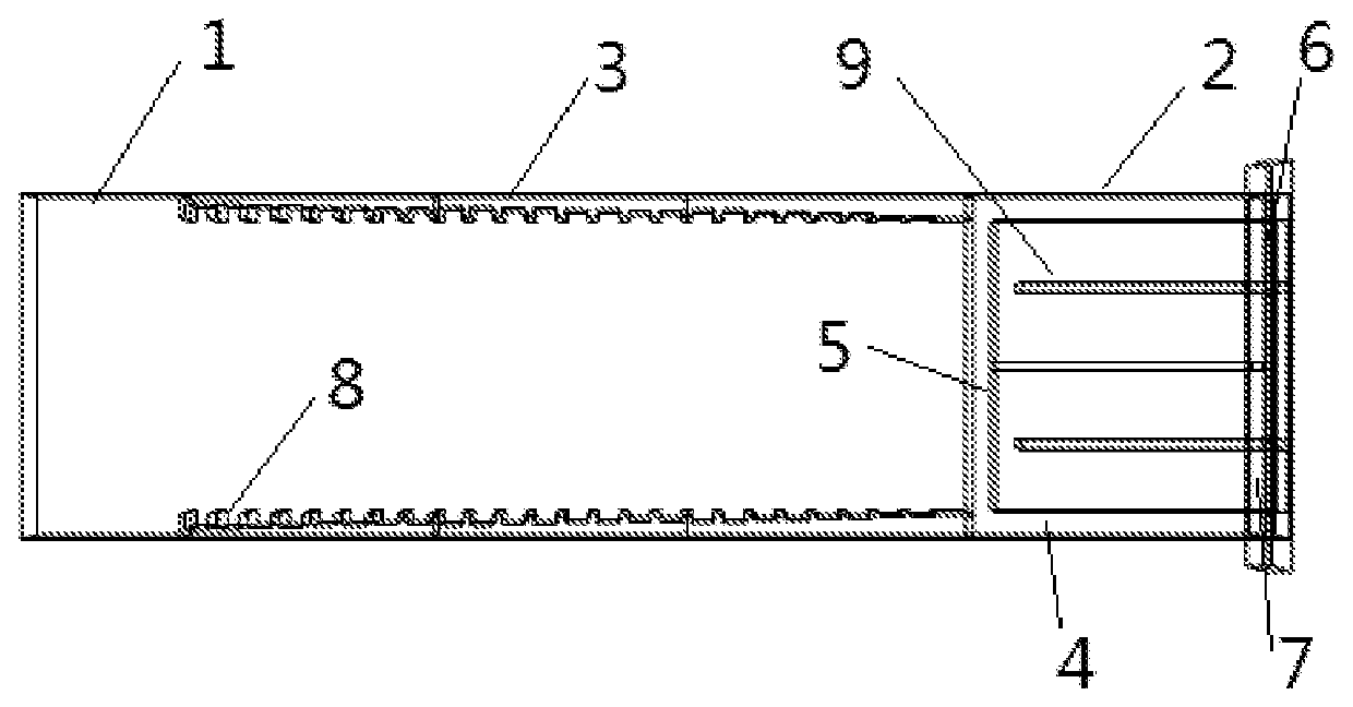
[0018]Referring to the FIGURE, according to the first preferred embodiment, a meta-surface water load comprises a waveguide section 1, a water load section 2 and two meta-surface plates 3, wherein: the water load section 2 is arranged at a rear end of the waveguide section 1; the two meta-surface plates 3 are arranged opposite on inner walls of two narrow sides of the waveguide section 1; the water load section 2 comprises a metal casing 4, a ceramic partition 5, a water inlet 6 and a water outlet 7; the metal casing 4 is mounted at the rear end of the waveguide section 1; cooling liquid flows in the metal casing 4, entering from the water inlet 6 and leaving from the water outlet 7; the ceramic partition 5 is for separating interior of the waveguide section 1 and interior of the metal casing 4; a relative permittivity of materials from front to rear of each meta-surface plate 3 is progressively increased, so that microwave in the waveguide section 1 is propagated to the water load ...

second preferred embodiment

[0019]Referring to the FIGURE, according to the second preferred embodiment, a meta-surface water load comprises a waveguide section 1, a water load section 2 and two meta-surface plates 3, wherein: the water load section 2 is arranged at a rear end of the waveguide section 1; the two meta-surface plates 3 are arranged opposite on inner walls of two narrow sides of the waveguide section 1; the water load section 2 comprises a metal casing 4, a ceramic partition 5, a water inlet 6 and a water outlet 7; the metal casing 4 is mounted at the rear end of the waveguide section 1; cooling liquid flows in the metal casing 4, entering from the water inlet 6 and leaving from the water outlet 7; the ceramic partition 5 is for separating interior of the waveguide section 1 and interior of the metal casing 4; a relative permittivity of materials from front to rear of each meta-surface plate 3 is progressively increased, so that microwave in the waveguide section 1 is propagated to the water load...

third preferred embodiment

[0021]Referring to the FIGURE, according to the third preferred embodiment, a meta-surface water load comprises a waveguide section 1, a water load section 2 and two meta-surface plates 3, wherein: the water load section 2 is arranged at a rear end of the waveguide section 1; the two meta-surface plates 3 are arranged opposite on inner walls of two narrow sides of the waveguide section 1; the water load section 2 comprises a metal casing 4, a ceramic partition 5, a water inlet 6 and a water outlet 7; the metal casing 4 is mounted at the rear end of the waveguide section 1; cooling liquid flows in the metal casing 4, entering from the water inlet 6 and leaving from the water outlet 7; the ceramic partition 5 is for separating interior of the waveguide section 1 and interior of the metal casing 4; a relative permittivity of materials from front to rear of each meta-surface plate 3 is progressively increased, so that microwave in the waveguide section 1 is propagated to the water load ...


PUM


Abstract

A meta-surface water load includes a waveguide section, a water load section and two meta-surface plates; the water load section is arranged at a rear end of the waveguide section; the two meta-surface plates are arranged opposite on inner walls of two narrow sides of the waveguide section; the water load section includes a metal casing, a ceramic partition, a water inlet and a water outlet; the metal casing is mounted at the rear end of the waveguide section; cooling liquid flows in the metal casing, entering from the water inlet and leaving from the water outlet; the ceramic partition is for separating interior of the waveguide section and interior of the metal casing; a relative permittivity of materials from front to rear of each meta-surface plate is progressively increased, so that microwave in the waveguide section is propagated to the water load section in one direction.

Description

CROSS REFERENCE OF RELATED APPLICATION[0001]The application is a continuation application of a PCT application No. PCT / CN2021 / 080943, filed on Mar. 16, 2021; and claims the priority of Chinese Patent Application CN 202011423274.3, filed to the China National Intellectual Property Administration (CNIPA) on Dec. 8, 2020, the entire content of which are incorporated hereby by reference.BACKGROUND OF THE PRESENT INVENTIONField of Invention[0002]The present invention relates to a technical field of microwave application, and more particularly to a meta-surface water load.Description of Related Arts[0003]In the industrial application of microwave energy, there exists more or less microwave reflection. Thus, it is necessary to arrange a load on the circulator to absorb the reflected microwave, thereby protecting the microwave source. The water load, as a common terminal matching load, comprises a waveguide transmission section and a microwave absorption cavity section, wherein: an interior...

Claims


Application Information

Patent Timeline
IPC IPC(8): H01P1/30H01P3/16
CPCH01P1/30H01P3/16H01P1/262H01P1/264
Inventor ZHU, HUACHENGYANG, YANG
Owner SICHUAN UNIV
Why Eureka
Try Eureka