
Magnetic cooling roll

a cooling roll and magnetic technology, applied in the field of magnetic cooling rolls, can solve the problems of increasing the number of rolls, so as to reduce or suppress the unevenness of contact, improve the efficiency of cooling system, and improve the uniformity of conta

Active Publication Date: 2021-10-28
ARCELORMITTAL INVESTIGACION Y DESARROLLO SL
View PDF0 Cites 0 Cited by
  • Summary
  • Abstract
  • Description
  • Claims
  • Application Information

AI Technical Summary

Benefits of technology

The technical effects of this patent text are to improve the contact homogeneity and cooling homogeneity along the strip width by reducing or suppressing the contact unevenness between the roll and the strip. Additionally, to improve the efficiency of the cooling system.

Problems solved by technology

However, by using the above equipment, the strip is not sufficiently in contact with to the roll in order to overcome the potential flatness defects of the strip and thus its flatness is worsened during the cooling and the quality of the strip is consequently degraded.
Moreover, the cooling system does not permit to sufficiently and homogeneously cool the strip leading to temperature variations along the strip width, especially between the edges and the center of the strip.
Furthermore, due to the arrangement of the different parts of the cooling roll, the heat transfer coefficient is not optimal.

Method used


Image

  • Magnetic cooling roll
  • Magnetic cooling roll
  • Magnetic cooling roll

Examples


example 1

[0068]In order to verify that the temperature is more homogeneous after than before the cooling roll, the temperature difference between the temperature extremums along the strip width is compared before and after its cooling by the cooling roll.

[0069]If the difference between the hottest and the coldest point along the strip width is of 20° C. before the cooling roll and is of 10° C. after the cooling roll then the temperature gap difference is of 10° C. If the difference between the hottest and the coldest point along the strip width is of 20° C. before the roll and is of 30° C. after the roll then the temperature gap difference is of −10° C.

[0070]This means that the obtained temperature gap difference is superior to 0 then the temperature homogeneity along the strip width has been increased. Moreover, higher is the temperature gap difference value, better is the temperature homogeneity improvement.

[0071]It is clear from the reading of the graph, in FIG. 11, that the temperature h...

example 2

[0072]In order to verify the improvement of the temperature homogeneity along the strip width, the roll temperature profiles along different width 11′ has been measured, as it can be seen in FIG. 12. The temperature is uniform along the section in contact with the strip width 12′. Consequently, the strip is uniformly cooled in the width direction so the border and the center of the strip width are at the same temperature. This results clearly demonstrates the expected results of this invention and an improvement compared to the state of the art.

example 3

[0073]In order to assess the ratio between the gap height and the magnet width, the attraction force generated by the magnets on the outer surface of the roll is determined in function of this ratio.

[0074]From this graph, plotted in FIG. 13, it is clear that the optimal range is for a ratio following this equation:

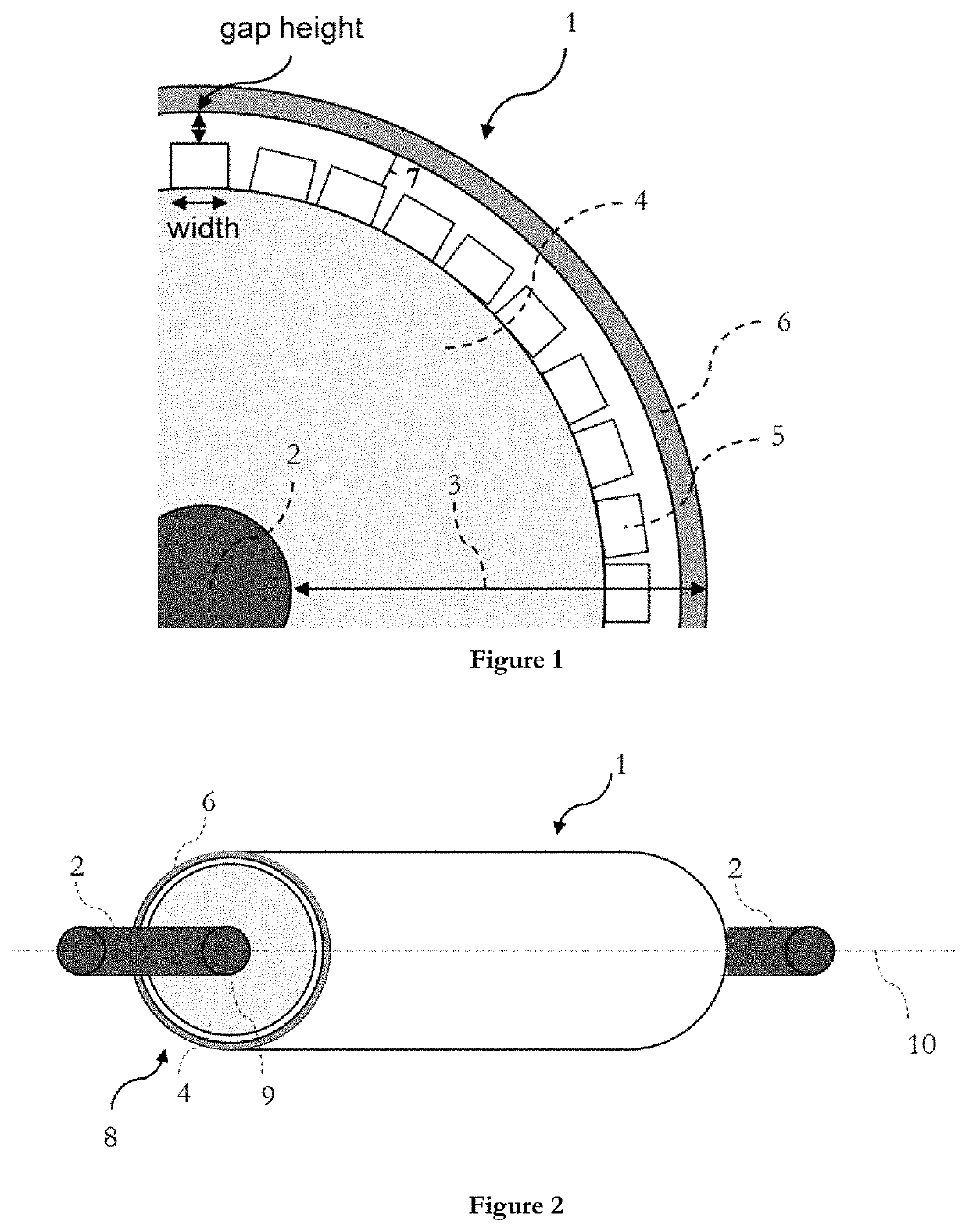
gap height×1.1 magnet width gap height×8.6, corresponding to approximately 50% of the maximum attraction force.


PUM

PropertyMeasurementUnit
speedaaaaaaaaaa
speedaaaaaaaaaa
temperatureaaaaaaaaaa

Abstract

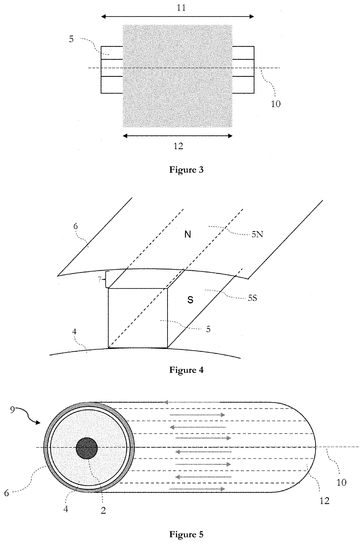
A cooling roll including an axle and a sleeve, the sleeve having a length and a diameter and being structured as follows: an inner cylinder, a plurality of magnets disposed along at least a portion of the inner cylinder length, each magnet being defined by a width, a height and a length, a cooling system surrounding at least a portion of the plurality of magnets, the cooling system and the plurality of magnets being separated by a gap defined by a height, the gap height being the smallest distance between a magnet and the cooling system above, the magnets having a width such that the following formula is satisfied: gap height x 1.1 magnet width gap height×8.6.

Description

[0001]The present invention relates to an equipment for cooling down a continuously moving metallic strip. This invention is particularly suited for the cooling of steel sheets, during metallurgical processes.BACKGROUND[0002]In a hot steel strip cooling process, cooling the strip with a cooling roll is a known process. Such cooling rolls can be used at various step of the process, e.g.: downstream a furnace or a coating bath. The strip is majorly cooled down due to the thermal conduction between the cooled cooling roll and the strip. However, the efficiency of such a technique is greatly impacted by the flatness of the strip and the surface contact between the roll and the strip. The strip flatness is worsened when there is a contact unevenness between the roll and the strip along the strip width due to uneven cooling rates.[0003]Patent JPH04346628 relates to an apparatus, a roll, for cooling down a strip. Magnets are provided inside a roll body continuously or at suitable intervals...

Claims


Application Information

Patent Timeline
Patent Type & Authority Applications(United States)
IPC IPC(8): C21D9/573
CPCC21D9/5737F27B9/145F27D3/026F27D2003/0039F27D2009/007C21D9/0012C21D9/563C21D11/005C21D9/00C21D9/56C21D9/573F27B9/14F27D3/02
Inventor HAMIDE, MAKHLOUFANDERHUBER, MARCDAUBIGNY, ALAINLUTZ, LAURENT
Owner ARCELORMITTAL INVESTIGACION Y DESARROLLO SL
Learn More