Managing the Charging of a Fleet of Vehicles to Align with a Renewable Energy Supply Curve for an Electric Grid

a technology for renewable energy supply and electric grid, applied in the direction of electric vehicle charging technology, charging stations, transportation and packaging, etc., can solve the problems of increasing the number of vehicles that are not easily controlled, creating new consumption patterns, and generally time- and/or weather-dependent energy output from renewable energy sources

Pending Publication Date: 2021-11-04
BAYERISCHE MOTOREN WERKE AG
View PDF0 Cites 7 Cited by
  • Summary
  • Abstract
  • Description
  • Claims
  • Application Information

AI Technical Summary

Benefits of technology

[0003]According to an embodiment of the disclosed subject matter a computer-implemented method may include receiving, via a network, a charging requirement from a first entity. The charging requirement may be based on an available power output capacity of the first entity. The method may further include receiving, via the network, ramp data from a second entity. The ramp data may be based on an anticipated power output of an energy source. The method may further include determining, via a processor, a charge plan based on the charging requirement and the ramp data. The charge plan may specify a timing of charging or discharging the first entity. The method may further include transmitting, via the network, the charge plan to the first entity. The method may further include receiving, via the network, load data from the first entity. The load data may be based on supply or consumption of power by the first entity and the charge plan. The ramp data may indicate the anticipated power output of a renewable energy source over a plurality of time periods. The second entity may be a vehicle comprising a charge storage device. The charging requirement may indicate a quantity of charge needed to restore the power output capacity to a predetermined level. The predetermined level may be based on an anticipated next use of the vehicle. The charge plan may instruct the first entity to discharge a charge storage device during a time when the ramp data indicates the anticipated power output will be less than a threshold amount. The charge plan may instruct the first entity to defer charging a charge storage device until the ramp data indicates the anticipated power output will meet a threshold amount. The method may further include determining, via the processor, a minimum threshold of charge of the first entity based on the charging requirement. The charge plan may instruct the first entity to charge a charge storage device to the minimum threshold of charge, and after the charge storage device reaches the minimum threshold, to subsequently charge the charge storage device only when the ramp data indicates an anticipated power output will meet a threshold amount. The method may further include receiving, via the network, updated ramp data from the second entity. The method may further include determining, via the processor, an updated charge plan based on the updated ramp data. The method may further include transmitting, via the network, the updated charge plan to the first entity. The method may further include receiving, via the network, second load data from a third entity. The second load data may be based on supply or consumption by the third entity and a second charge plan determined by the processor. The method may further include generating, via the processor, a load profile based on the load data by aggregating the load data with the second load data. The load profile may comprise an aggregate electrical demand or electrical supply of the first entity and the third entity. The method may further include transmitting, via the network, a load profile to the second entity. The charge plan may instruct the first entity to begin charging at a predetermined time and at a variable charging rate. The charging rate may increase when the ramp data indicates an anticipated power output of the energy source will increase or may decrease when the ramp data indicates an anticipated power output of the energy source will decrease.

Problems solved by technology

While grid operators can vary the energy output of fuel-based generators to meet demand, the energy output from renewable energy sources are generally time and / or weather-dependent and thus, not easily controlled.
Solar energy is an example of a renewable energy source that presents challenges to balancing the grid both due to its inherent limited duration and weather-based output volatility.
Additionally, the ever-increasing adoption of hybrid and electric vehicles has shifted consumer demand for energy from fuel stations to the grid along with creating new patterns of consumption.

Method used


Image

  • Managing the Charging of a Fleet of Vehicles to Align with a Renewable Energy Supply Curve for an Electric Grid
  • Managing the Charging of a Fleet of Vehicles to Align with a Renewable Energy Supply Curve for an Electric Grid
  • Managing the Charging of a Fleet of Vehicles to Align with a Renewable Energy Supply Curve for an Electric Grid

Examples


Embodiment Construction

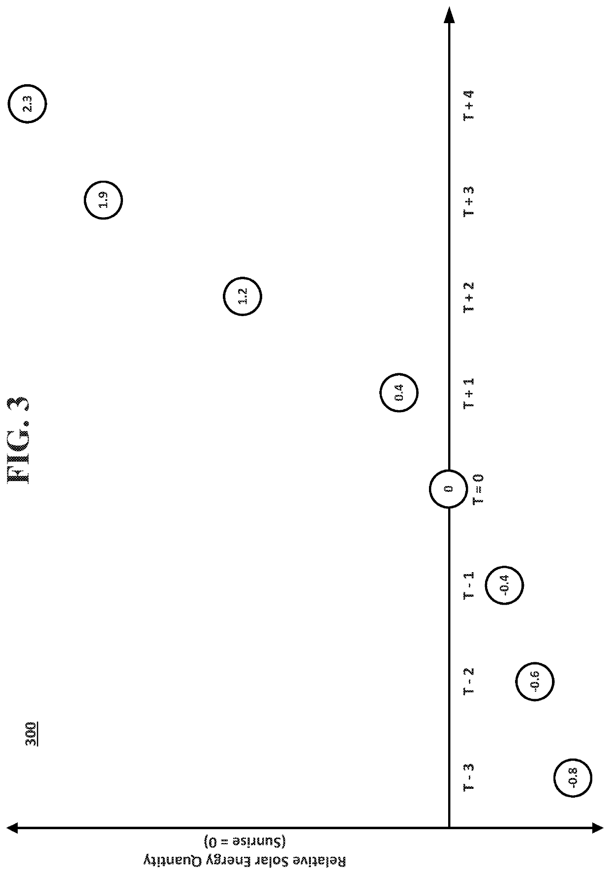
[0011]Renewable energy sources may complicate the act of balancing the grid both because of their generally variable output timing and the limited controllability of the output capacity. In the case of solar energy, for example, increasing levels of energy output when the sun rises may necessitate grid operators to find a correspondingly increasing level of demand. Where consumer demand does not coincide with the increasing supply, grid operators may address this issue in a variety of ways. For example, grid operators may direct the surplus solar energy to a stationary energy storage device, such as a battery, which may come with significant costs. Grid operators may curtail solar energy generation by disconnecting or deactivating solar panels, which may be an inefficient use of the solar panel infrastructure. Similarly inefficient, grid operators may artificially create electrical demand by needlessly activating electrical loads where possible. Grid operators may also respond to in...


PUM


Abstract

A computing system can facilitate cooperation between a utility and a fleet of vehicles. The system can receive a charging requirement from a vehicle. The charging requirement can be based on an available power output capacity of a battery pack of the vehicle. The system can receive solar ramp data from a utility. The solar ramp data can be based on an anticipated power output of a solar energy source. The system can determine a charge plan based on the charging requirement and the solar ramp data and specify a timing of charging or discharging the vehicle. The system can transmit the charge plan to the vehicle. The system can receive load data from the vehicle based on supply or consumption of power by the vehicle and the charge plan.

Description

BACKGROUND[0001]State and local governments have established ambitious targets specifying increased proportions of energy to be generated by renewable sources. Electric grid operators are tasked with ensuring that consumer demand for electrical energy is balanced by supply from the grid. While grid operators can vary the energy output of fuel-based generators to meet demand, the energy output from renewable energy sources are generally time and / or weather-dependent and thus, not easily controlled.[0002]Solar energy is an example of a renewable energy source that presents challenges to balancing the grid both due to its inherent limited duration and weather-based output volatility. Additionally, the ever-increasing adoption of hybrid and electric vehicles has shifted consumer demand for energy from fuel stations to the grid along with creating new patterns of consumption.BRIEF SUMMARY[0003]According to an embodiment of the disclosed subject matter a computer-implemented method may in...

Claims


Application Information

Patent Timeline
Patent Type & Authority Applications(United States)
IPC IPC(8): B60L53/63B60L53/62B60L53/66
CPCB60L53/63B60L53/66B60L53/62B60L53/51B60L53/68Y02E60/00Y02T10/70Y02T10/7072Y02T90/12Y02T90/16Y04S10/126
Inventor BATIR, SEANLANGTON, ADAMPEASE, HENRY
Owner BAYERISCHE MOTOREN WERKE AG
Why Eureka
Try Eureka