Steering Device having a Connector Unit for Making Electrical Contact with a Steering Sensor Unit

a technology of steering sensor and connector unit, which is applied in the direction of coupling device connection, force/torque/work measurement apparatus, instruments, etc., can solve the problems of time-consuming assembly process and complicated assembly process, and achieve simple and/or reliable coupling of plug-in elements and simple assembling of plug-in connector units.

Pending Publication Date: 2021-11-04
ROBERT BOSCH GMBH
View PDF0 Cites 1 Cited by
  • Summary
  • Abstract
  • Description
  • Claims
  • Application Information

AI Technical Summary

Benefits of technology

[0016]According to a further design embodiment, it is proposed that the steering device has a positioning unit which in the assembly procedure of the plug connector unit is provided for establishing a defined orientation of the plug connector unit relative to the steering gear housing and / or the housing cover. To this end, the positioning unit can in particular comprise at least one shaped element such as, for example, an elevation and / or a depression, and / or at least one assembly marking, for example in the form of a pictogram. Particularly simple assembling of the plug connector unit can in particular be achieved on account thereof.
[0017]A particularly simple and / or reliable coupling of the plug-in elements can in particular be achieved when the steering device has a guide unit which in the assembly procedure of the plug connector unit is provided for guiding the plug connector unit relative to the steering gear housing and / or the housing cover.

Problems solved by technology

This construction however leads to a complicated and time-consuming assembly process which requires in particular a plurality of assembly steps as well as manual plug-fitting of the sensor cable during the assembly process of the steering shaft, or of the steering sensor, respectively.

Method used


Image

  • Steering Device having a Connector Unit for Making Electrical Contact with a Steering Sensor Unit
  • Steering Device having a Connector Unit for Making Electrical Contact with a Steering Sensor Unit
  • Steering Device having a Connector Unit for Making Electrical Contact with a Steering Sensor Unit

Examples


Embodiment Construction

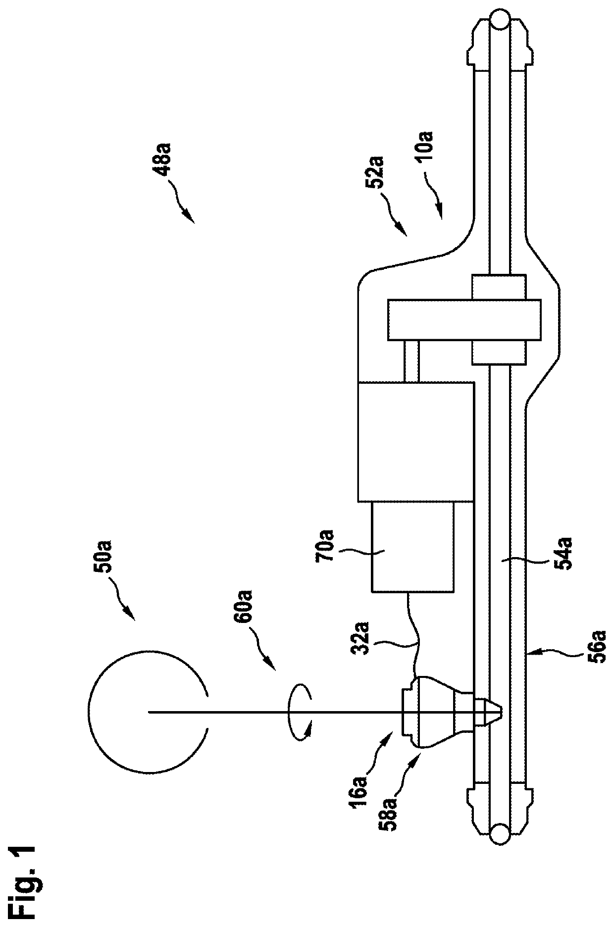
[0033]FIG. 1 shows a purely exemplary steering system 48a in a schematic illustration. The steering system 48a is configured as an electrically assisted steering system and accordingly has an electrical servo assistance. Furthermore, the steering system 48a is provided for use in a vehicle (not illustrated), in particular a motor vehicle. The steering system 48a in an installed state is operatively connected to vehicle wheels of the vehicle and is provided for influencing a travel direction of the vehicle. In principle, it is of course also conceivable for a steering system to be configured as a hydraulically assisted steering system, in particular having a hydraulic servo assistance.

[0034]The steering system 48a has a steering device. The steering device comprises a steering handle 50a, in the present case configured in an exemplary manner as a steering wheel, for applying a manual steering torque, as well as a steering gear 52a which is known per se and provided for converting a s...


PUM

PropertyMeasurementUnit
angleaaaaaaaaaa
angleaaaaaaaaaa
angleaaaaaaaaaa

Abstract

A steering device includes: a steering gear housing, which provides a sensor accommodation region; a steering sensor unit, which is situated in the sensor accommodation region when installed; a housing cover, which is provided to cover the sensor accommodation region in the axial direction when installed; and a connector unit, which can be situated in a contact recess in the steering gear housing or in the housing cover, for making, in particular direct, electrical contact with the steering sensor unit during the process of installing the connector unit. The connector unit includes a plug unit with at least one plug element for connection to the steering sensor unit, and a support unit. The connector unit also includes an elastic compensation unit, which is connected fixedly to the plug element and to the support unit and is provided to resiliently support the plug element.

Description

PRIOR ART[0001]The invention proceeds from a steering device according to the preamble of claim 1 and from a method for assembling a steering device according to the preamble of claim 15. The invention moreover relates to a steering system having such a steering device and to a connector unit of such a steering device.[0002]Steering systems for motor vehicles, having steering sensors which for determining a steering angle and / or a steering torque exerted on the steering shaft are disposed on a steering shaft, are known from the prior art. Steering sensors of this type typically comprise a sensor housing which is connected to the steering shaft as well as a sensor element which is disposed in the sensor housing.[0003]In a known assembly process, the sensor housing is pushed onto the steering shaft and fastened to the steering shaft. The steering shaft conjointly with the sensor housing is subsequently inserted into an assembly opening of a steering gear housing, wherein a sensor cabl...

Claims


Application Information

Patent Timeline
Patent Type & Authority Applications(United States)
IPC IPC(8): B62D5/04B62D6/10H01R13/56H01R13/631G01L5/22
CPCB62D5/0403B62D6/10H01R13/562H01R13/6273G01L5/221H01R2201/26H01R13/631B62D15/0215
Inventor MATTUS, WALDEMARWEBER, MARTENISDEBSKI, TOBIASSEIBOLD, PHILIPP
Owner ROBERT BOSCH GMBH
Why Eureka
Try Eureka