Methods and systems for a magnetic motor x-ray assembly

a technology of magnetic motors and x-ray assemblies, applied in the field of x-ray tubes, can solve the problems of placing stringent bearing demands, and achieve the effect of enhancing motor performance and reducing the footprint of x-ray tube motors

Active Publication Date: 2021-11-11
GE PRECISION HEALTHCARE LLC
View PDF0 Cites 1 Cited by
  • Summary
  • Abstract
  • Description
  • Claims
  • Application Information

AI Technical Summary

Benefits of technology

[0004]In one embodiment, an x-ray tube includes a rotor with a non-magnetic core forming a continuous unit with at least one of a retention sleeve and a bearing assembly sleeve and one or more magnets disposed in the core and maintained in place by the retention sleeve. In this way, a footprint of the x-ray tube motor may be decreased while motor performance is enhanced.

Problems solved by technology

This places stringent demands on the bearings and the material forming the anode structure, i.e., the anode target and the shaft supporting the target.

Method used


Image

  • Methods and systems for a magnetic motor x-ray assembly
  • Methods and systems for a magnetic motor x-ray assembly
  • Methods and systems for a magnetic motor x-ray assembly

Examples


Embodiment Construction

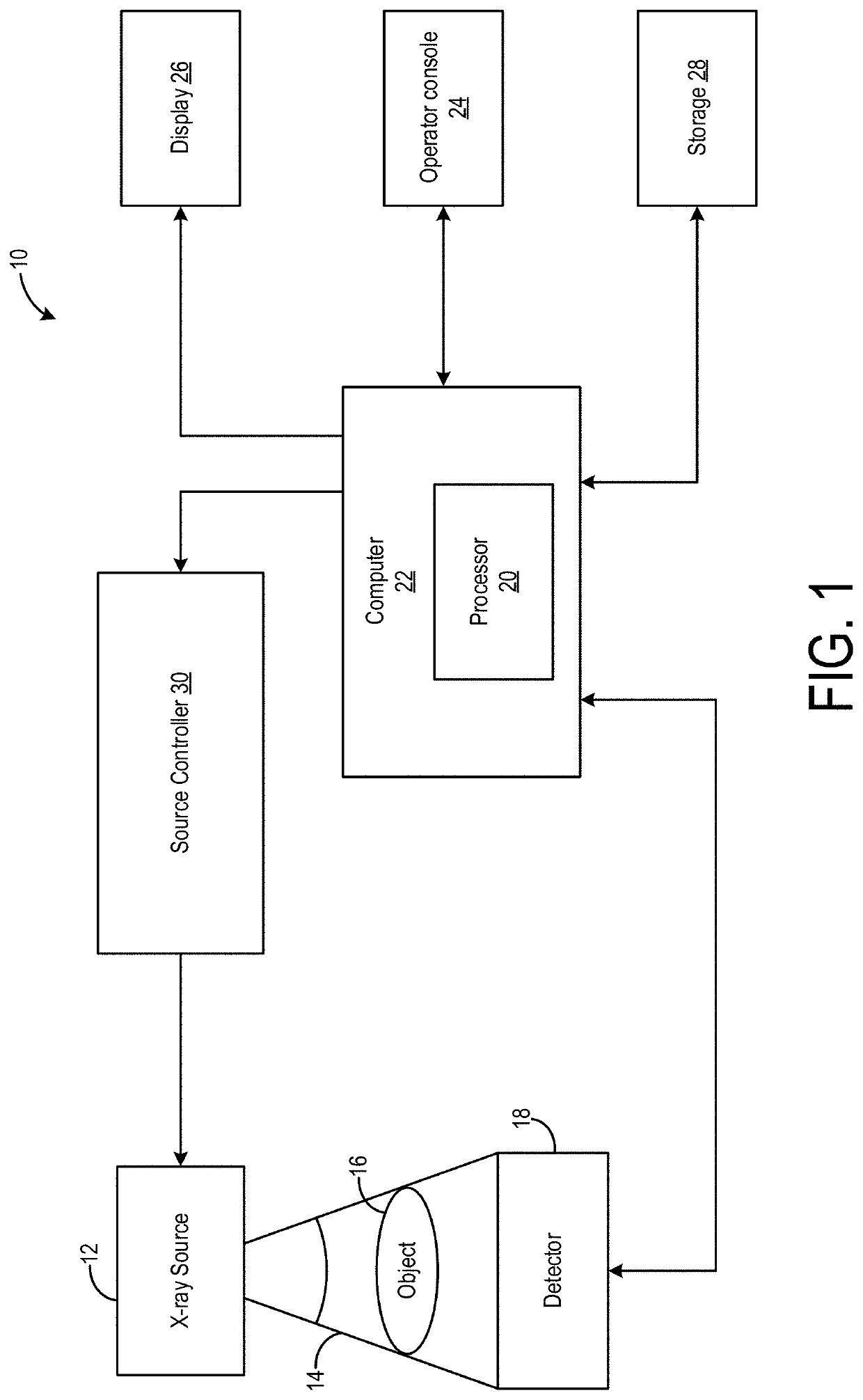
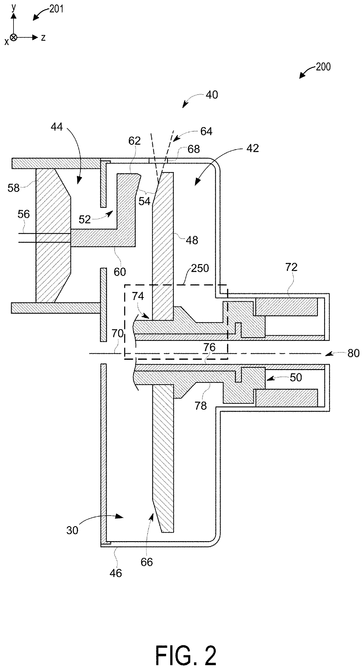
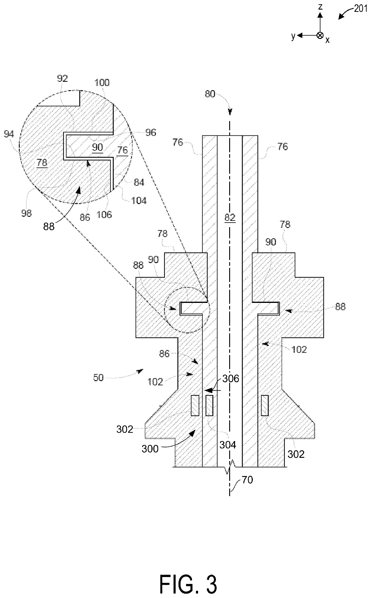
[0036]The following description relates to various embodiments of an x-ray tube for an imaging system. The x-ray tube may be included in an x-ray imaging system, an example of which is shown in FIG. 1. In one example, the x-ray imaging system may be a CT imaging, as shown in FIG. 12, which may include a rotating gantry. The x-ray imaging system includes an x-ray source or tube to generate irradiating x-ray beams. A cross-sectional view of the x-ray tube is shown in FIG. 2, the x-ray tube including a journal bearing, as illustrated in FIG. 3 in greater detail. The journal bearing of FIG. 3 may be configured as a liquid bearing assembly, including magnets positioned in a sleeve and a shaft of the bearing assembly. In another example, as shown in FIG. 4, the journal bearing may instead have a ball bearing assembly. Magnets may also be disposed in a rotor core of the PMSM, providing various benefits described further below. As such, the motor may be a permanent magnet synchronous motor ...


PUM


Abstract

Various methods and systems are provided for an x-ray imaging system. In one example, an x-ray tube of the imaging system includes a rotor with a core forming a continuous unit with at least one of a retention sleeve and a bearing assembly sleeve. The rotor further includes one or more magnets disposed in the core and maintained in place by the retention sleeve.

Description

FIELD[0001]Embodiments of the subject matter disclosed herein relate to x-ray tubes and more particularly to permanent magnet x-ray assemblies.BACKGROUND[0002]X-ray systems may include an x-ray tube, a detector, and a support structure for the x-ray tube and the detector. In operation, an imaging table, on which an object is positioned, may be located between the x-ray tube and the detector. The x-ray tube typically emits radiation, such as x-rays, toward the object. The radiation passes through the object on the imaging table and impinges on the detector. As radiation passes through the object, internal structures of the object cause variances in the attenuation of the radiation received at the detector. The detector then emits data received, and the system translates the radiation variances into an image, which may be used to evaluate the internal structure of the object. The object may include, but is not limited to, a patient in a medical imaging procedure and an inanimate objec...

Claims


Application Information

Patent Timeline
Patent Type & Authority Applications(United States)
IPC IPC(8): H01J35/10
CPCH01J35/103H01J2235/1086H01J2235/1026H01J35/101H01J2235/1046H05G1/66H05G1/46H01J2235/085F16C32/064F16C37/002F16C2380/16H01J35/1024H01J35/104H01J2235/1073H01J2235/1208H01J2235/1204H01J2235/1266H01J35/106H01J35/107
Inventor TAPADIA, NIDHISHRINECULAES, VASILE BOGDANCROSS, ANDREW THOMASHUNT, IAN STRIDER
Owner GE PRECISION HEALTHCARE LLC
Why Eureka
Try Eureka