Supercharge Your Innovation With Domain-Expert AI Agents!

Surface Precision Defect Shaver

Active Publication Date: 2021-11-18
LOCKHEED MARTIN CORP
View PDF0 Cites 0 Cited by
  • Summary
  • Abstract
  • Description
  • Claims
  • Application Information

AI Technical Summary

Benefits of technology

The patent is about an apparatus and method for precision shaving, which can remove small amounts of excess material from the exterior of an aircraft. The apparatus includes an endmill cutter, a motor, and a coupler for positioning the cutter. A positioning slide and gears are also included. The technical effect of this patent is that it provides a tool for removing material with a high degree of precision.

Problems solved by technology

Traditional shaving systems are large, costly, imprecise, and ineffective with contoured surfaces.

Method used


Image

  • Surface Precision Defect Shaver
  • Surface Precision Defect Shaver
  • Surface Precision Defect Shaver

Examples


Embodiment Construction

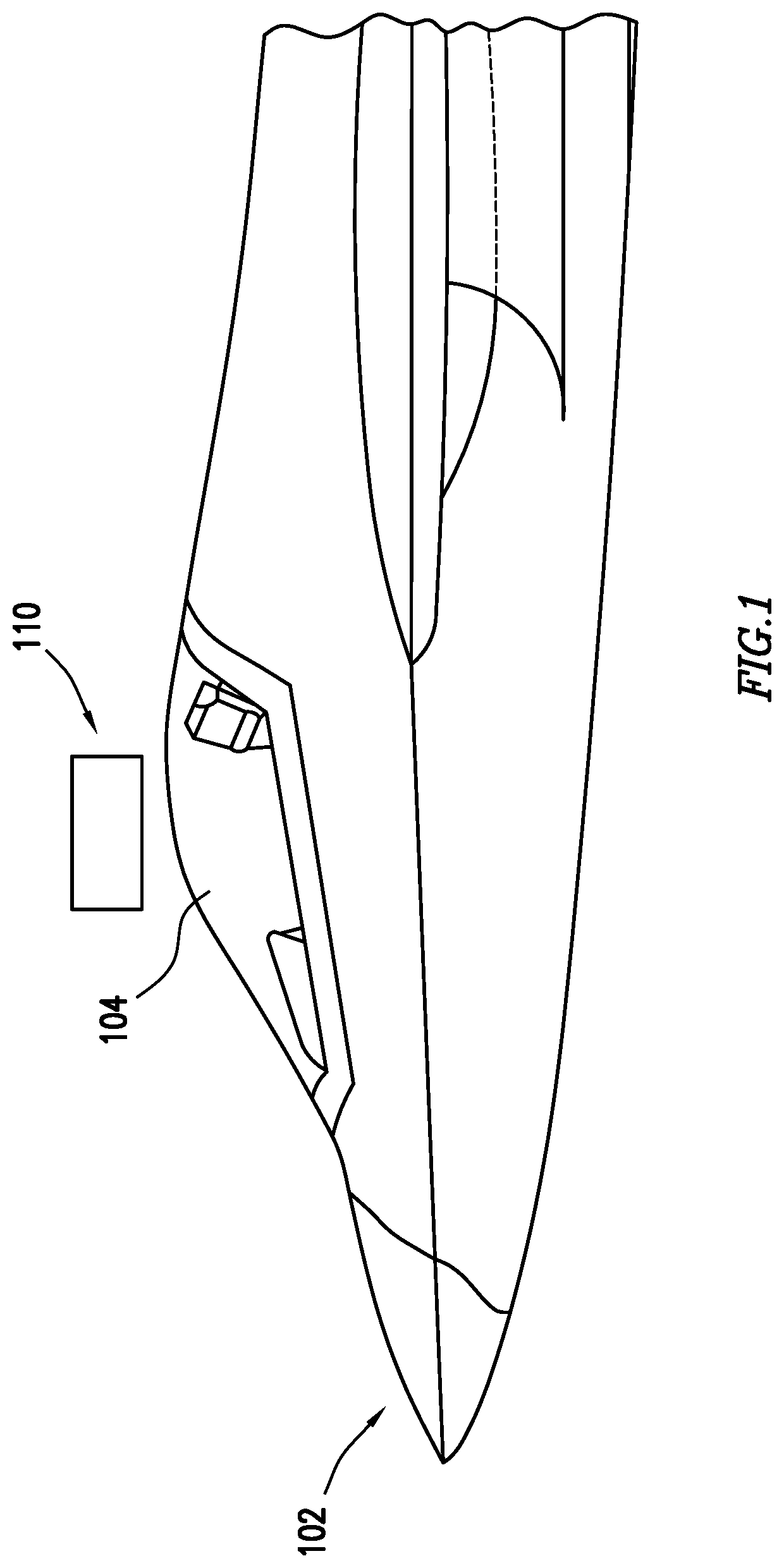
[0010]The teachings of the disclosure recognize that existing shaving systems are large, costly, and difficult to use. Existing tools often require expensive robotics and programming, and they are unable to hold a tight enough tolerance to remove a small amount of material, such as 0.001 inches. Traditional systems often shave too little material from a surface or too deep into the surface, rendering the surface unusable. When implemented on an aircraft, existing tools are ineffective with contoured surfaces, such as the canopy over the cockpit. Further, many existing shaving systems only work with certain types of large motors that operate at a high rate of revolutions per minute (RPM). The above problems cause existing shaving tools to be imprecise and inflexible in different applications.

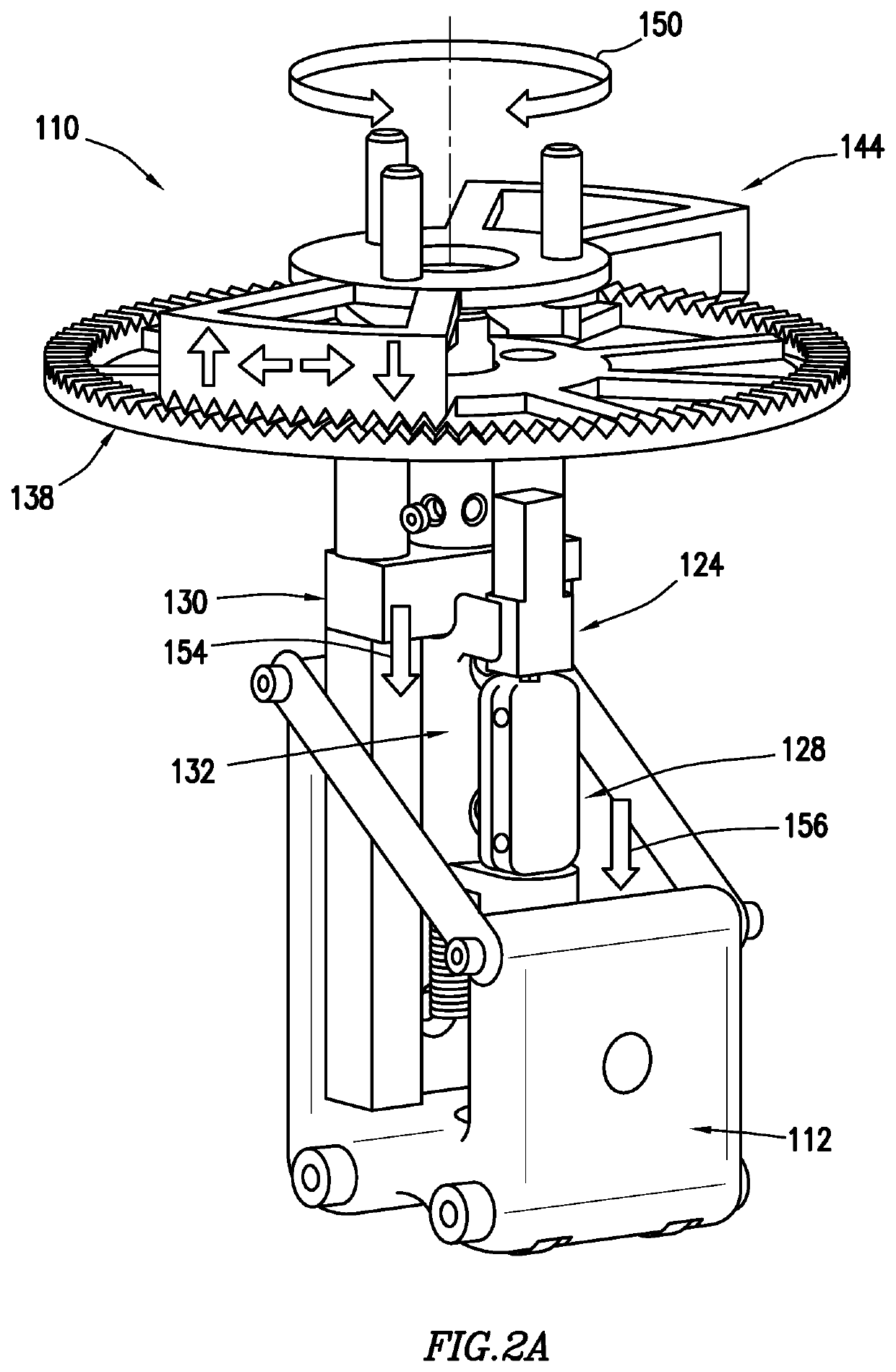
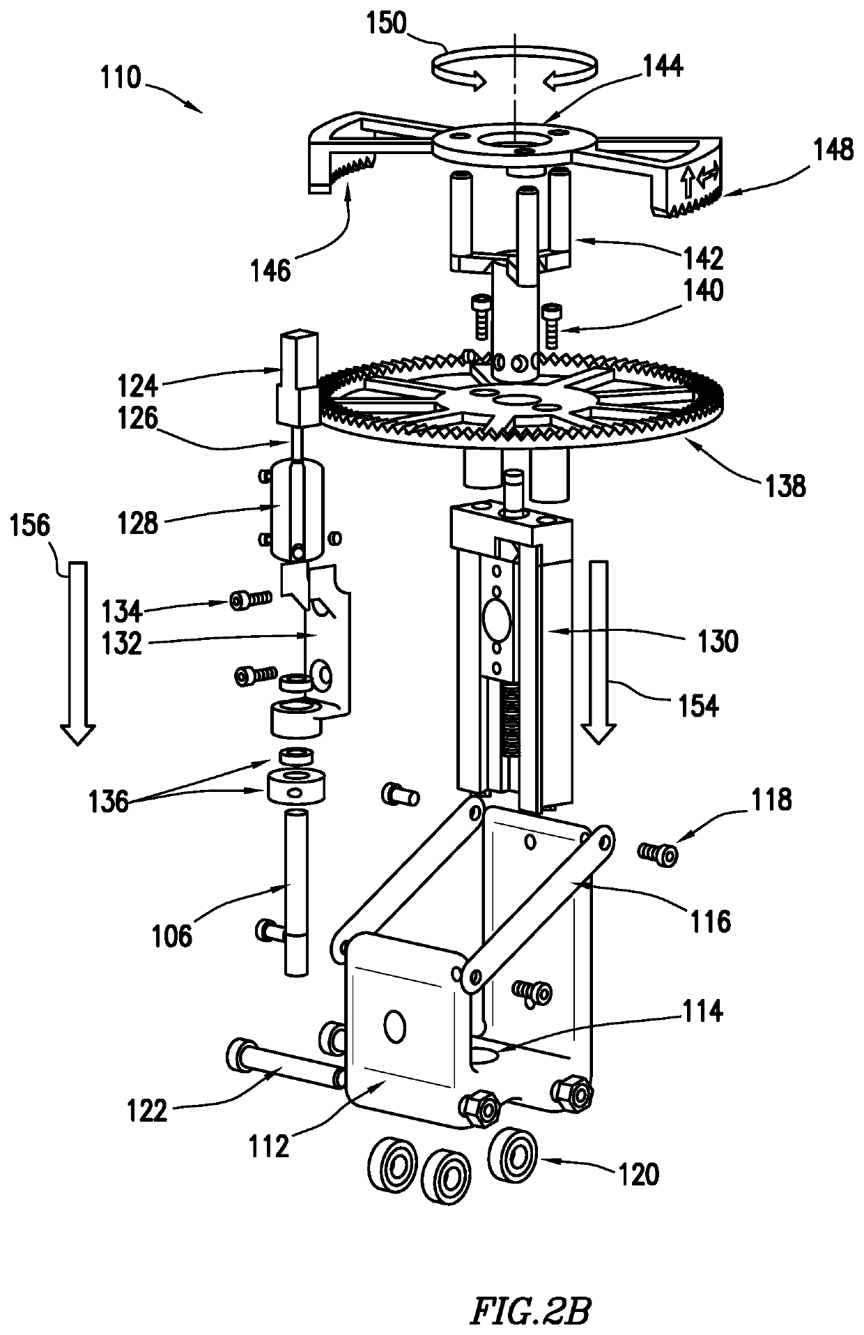
[0011]The teachings of the disclosure recognize that by incorporating certain modified components in the shaving system, these above problems can be addressed. For example, a modified gear system...


PUM

PropertyMeasurementUnit
Lengthaaaaaaaaaa
Lengthaaaaaaaaaa
Angleaaaaaaaaaa

Abstract

An apparatus for precision shaving is provided. In one embodiment, the apparatus includes an endmill cutter, a base frame, and a motor adjacent to the base frame and having a shaft on one end. A coupler is positioned between the shaft and the endmill cutter. A positioning slide is housed within the base frame and a coupler frame and a first gear are fastened to the positioning slide. A second gear is adjacent to the first gear, the second gear having a set of first teeth and a set of second teeth positioned opposite the set of first teeth. The set of first teeth and the set of second teeth are separated by a gap.

Description

TECHNICAL FIELD[0001]This disclosure relates in general shaving systems for aircraft and more particularly to a surface precision defect shaver.BACKGROUND[0002]Precision shaving systems may be used to remove a defect from a surface. In the context of aircraft, precision shaving systems may be used to remove a defect from the exterior of an aircraft, such as the canopy over the cockpit. Traditional shaving systems are large, costly, imprecise, and ineffective with contoured surfaces.SUMMARY OF THE DISCLOSURE[0003]According to one embodiment, an apparatus for precision shaving is provided. The apparatus includes an endmill cutter, a base frame, and a motor adjacent to the base frame, the motor having a shaft on one end. A coupler is positioned between the shaft and the endmill cutter. A positioning slide is housed within the base frame and a coupler frame and a first gear are fastened to the positioning slide. A second gear is adjacent to the first gear, the second gear having a set o...

Claims


Application Information

Patent Timeline
IPC IPC(8): B23C3/13B23C5/06
CPCB23C3/13B23C5/06B23C3/16B23C2255/00B23C1/20B23Q9/0014B23Q9/0028Y10T409/306608Y10T409/306496Y10T409/307952Y10T409/308176B23Q16/024
Inventor COFFEY, KEVIN AARONSTREET, STUART C.TWADDLE, STEVEN E.JENKINS, WILLIAM LYNN
Owner LOCKHEED MARTIN CORP
Features
  • R&D
  • Intellectual Property
  • Life Sciences
  • Materials
  • Tech Scout
  • Unparalleled Data Quality
  • Higher Quality Content
  • 60% Fewer Hallucinations
Learn More