Vehicle drive device

a technology of drive device and drive shaft, which is applied in the direction of electric devices, battery/fuel cell control arrangements, electric devices, etc., can solve the problems of reduced electric power utilization efficiency in the entire vehicle, increased costs, and complicated device structure, so as to prevent the device configuration from becoming complicated, reduce the electric power consumed by the power storage device, and prevent the device structure from becoming complicated

Pending Publication Date: 2021-11-25
AISIN CORP
View PDF0 Cites 2 Cited by
  • Summary
  • Abstract
  • Description
  • Claims
  • Application Information

AI Technical Summary

Benefits of technology

[0007]As described above, since the power storage device is heated by the heater, a reduction in performance of the power storage device due to the temperature is minimized, thereby making the rotary electric machine operate appropriately. However, with this configuration, it is necessary to separately provide a heater for heating the power storage device, resulting in a complicated device structure and hence an increase in costs. Moreover, since electric power is consumed by the heater, the utilization efficiency of electric power in the entire vehicle is reduced. This presents a problem in terms of energy saving of the vehicle. That is, there is a problem in appropriately heating a power storage device in a vehicle drive device including a rotary electric machine that includes a plurality of mutually independent coil sets, each including coils of a plurality of phases connected to each other, and serves as a drive power source for a vehicle.
[0010]According to this configuration, with the warm-up control, a current is applied to the coil set of the rotary electric machine via the inverter to cause the rotary electric machine and the inverter to generate heat. The generated heat is transferred to the power storage device via a heat transfer system, thereby heating the power storage device. Therefore, there is no need to separately provide a heater or other devices for heating the power storage device, thereby preventing the device structure from becoming complicated. Meanwhile, at least one of the coil sets of the rotary electric machine is subjected to the power running control, and at least one of the other coil sets is subjected to the regenerative control, while the warm-up control is performed. Accordingly, the electric power consumed by the power running control, excluding the electric power consumed by heat generation of the coils, can be collected by the regenerative control. This makes it possible to reduce the electric power of the power storage device consumed for heating the power storage device. Thus, with this configuration, it is possible to appropriately heat the power storage device in a low temperature environment, while preventing the device configuration from becoming complicated, and minimizing a reduction in electric power utilization efficiency.

Problems solved by technology

However, with this configuration, it is necessary to separately provide a heater for heating the power storage device, resulting in a complicated device structure and hence an increase in costs.
Moreover, since electric power is consumed by the heater, the utilization efficiency of electric power in the entire vehicle is reduced.
This presents a problem in terms of energy saving of the vehicle.
That is, there is a problem in appropriately heating a power storage device in a vehicle drive device including a rotary electric machine that includes a plurality of mutually independent coil sets, each including coils of a plurality of phases connected to each other, and serves as a drive power source for a vehicle.

Method used


Image

  • Vehicle drive device
  • Vehicle drive device
  • Vehicle drive device

Examples


Embodiment Construction

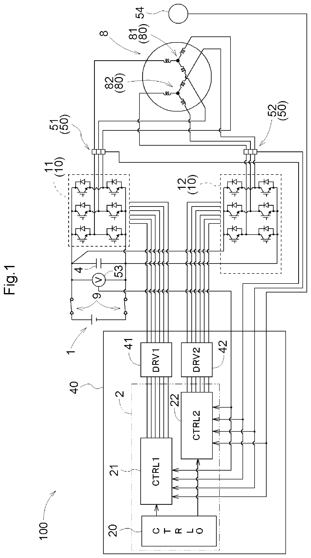
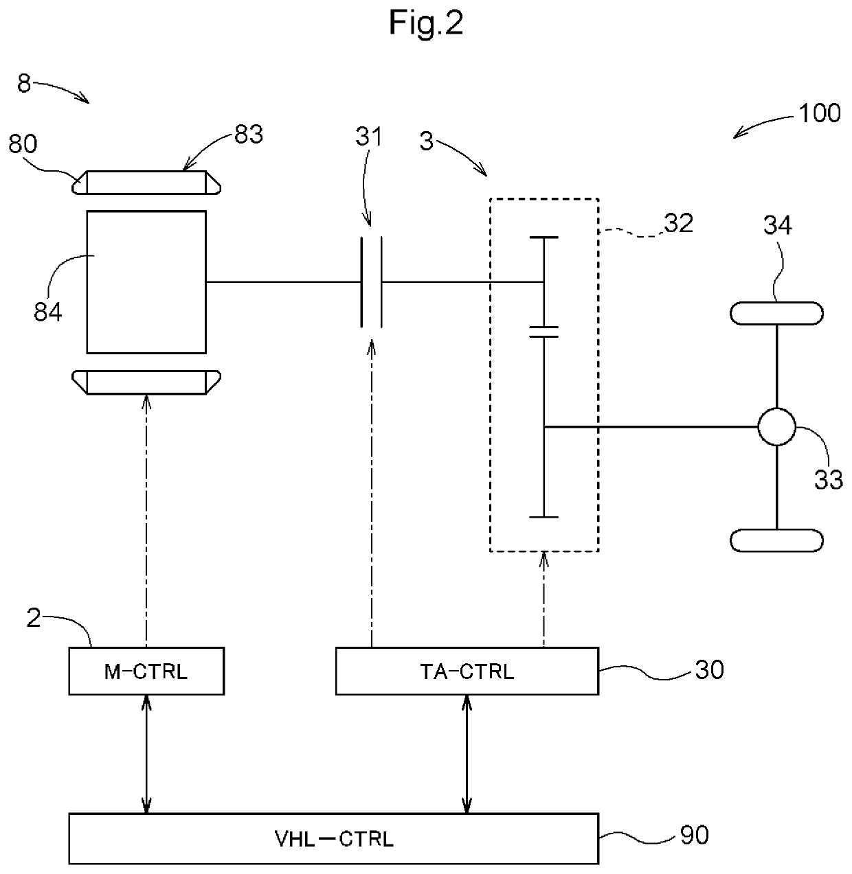
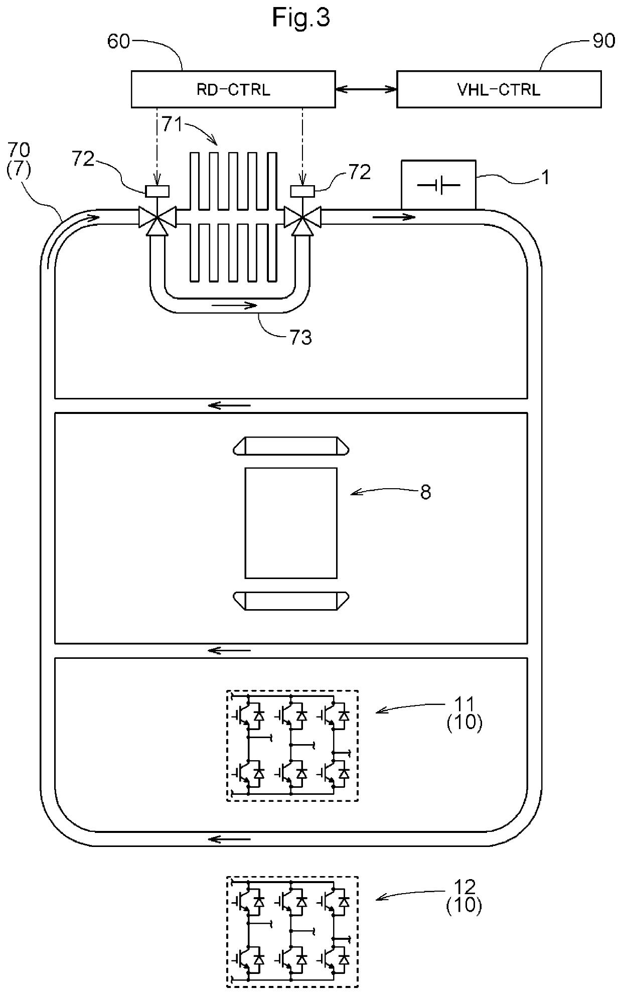
[0017]Hereinafter, an embodiment of a vehicle drive device will be described with reference to the drawings. FIG. 1 is a schematic diagram illustrating an electric system block that controls driving of a rotary electric machine 8. FIG. 2 is a train diagram illustrating an example of a power transmission path 3 connecting the rotary electric machine 8, serving as a drive power source for a vehicle, and wheels 34. FIG. 3 is a piping diagram illustrating an example of a refrigerant flow path 70 serving as a heat transfer system 7.

[0018]As illustrated in FIG. 1, a vehicle drive device 100 includes the rotary electric machine 8 that includes a plurality of mutually independent coil sets 80, each including coils of a plurality of phases connected to each other, and that serves as a drive power source for a vehicle. More specifically, the rotary electric machine 8 includes a single stator 83 and a single rotor 84, and the plurality of coil sets 80 are mounted on the single stator 83. The t...


PUM


Abstract

A power storage device is appropriately heated in a low temperature environment, while preventing device configuration from becoming complicated, and minimizing a reduction in electric power utilization efficiency. A vehicle drive device includes a rotary electric machine that includes plurality of mutually independent coil sets each including coils of plurality of phases connected to each other, plurality of inverters that independently control respective plurality of coil sets, a power storage device, heat transfer system that transfers heat to power storage device, and control device that controls plurality of inverters. The control device performs warm-up control by performing power running control on at least one of inverters and performing regenerative control on at least another of inverters in such a manner that power running torque resulting from power running control and regenerative torque resulting from regenerative control have different absolute values so that a rotor of rotary electric machine rotates.

Description

TECHNICAL FIELD[0001]The present disclosure relates to a vehicle drive device including a rotary electric machine that includes a plurality of mutually independent coil sets, each including coils of a plurality of phases connected to each other, and that serves as a drive power source for a vehicle.BACKGROUND ART[0002]Electric vehicles (EVs) equipped with a rotary electric machine as a vehicle drive source and hybrid vehicles (HEVs) equipped with a rotary electric machine and an internal combustion engine have been put into practical use. Japanese Unexamined Patent Application Publication No. 2000-41392 discloses a vehicle drive device including a rotary electric machine that includes a plurality of mutually independent coil sets, each including coils of a plurality of phases connected to each other, and serves as a drive power source for a vehicle. In this type of vehicle drive device, different inverters are connected to different coil sets. Accordingly, with respect to the curren...

Claims


Application Information

Patent Timeline
Patent Type & Authority Applications(United States)
IPC IPC(8): B60L50/16B60L58/24B60L3/00B60L50/51H02P29/62
CPCB60L50/16B60L58/24B60L3/003B60L3/0061B60L2240/36B60L50/51H02P29/62B60L2240/425B60L3/0046B60L3/04B60L7/14B60L2220/58H02P25/22H02P29/68Y02T10/64Y02T10/70Y02T10/72
Inventor KUME, AKIYASATO, YASUYUKIYAMADA, WATARU
Owner AISIN CORP
Why Eureka
Try Eureka