
Method and apparatus to provide connected, in-situ, comprehensive, and accurate lateral flow assays

a lateral flow assay and lateral flow technology, applied in the field of instruments, can solve the problems of increased risk of complications or death, delayed detection of medical conditions, treatment options, etc., and achieve the effect of increasing sensitivity

Pending Publication Date: 2021-11-25
XTRAVA INC
View PDF0 Cites 1 Cited by
  • Summary
  • Abstract
  • Description
  • Claims
  • Application Information

AI Technical Summary

Benefits of technology

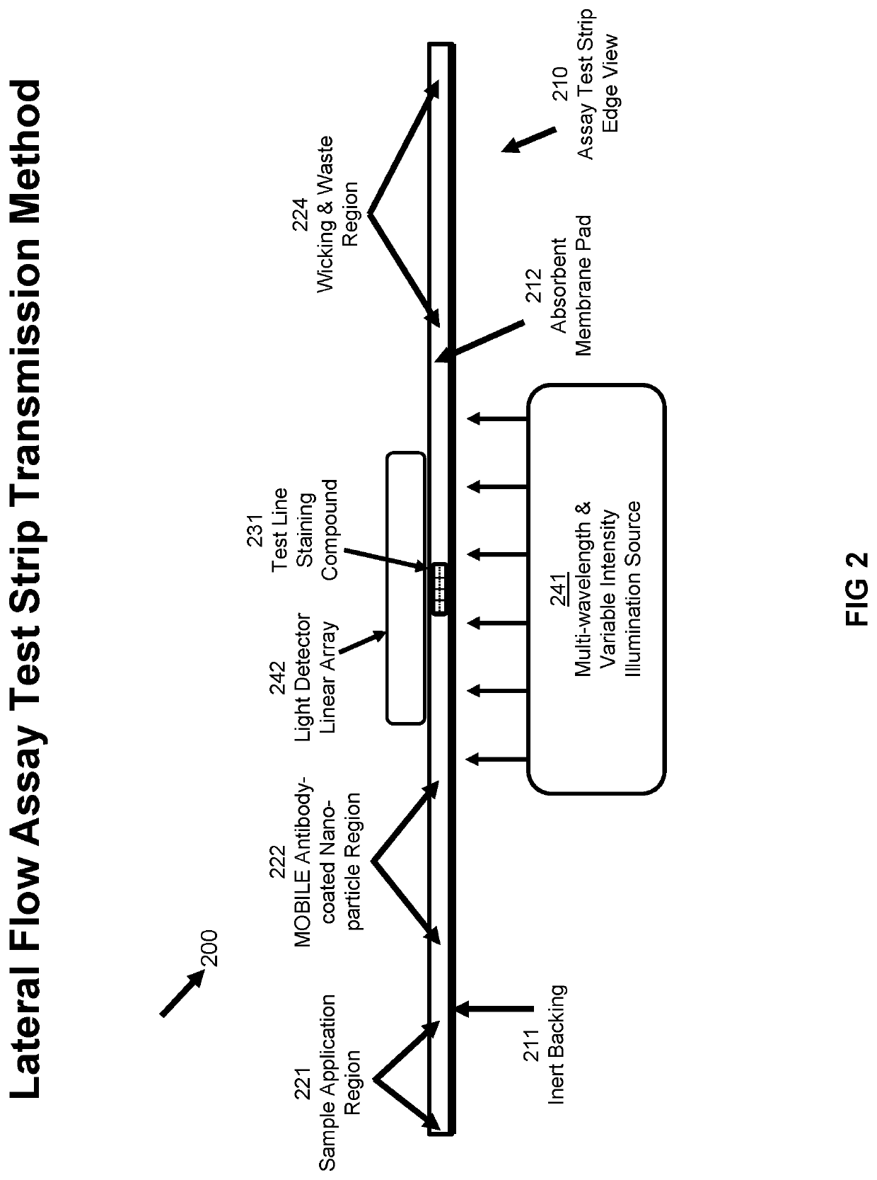
The Health Diagnostic Device contains features that improve the accuracy and sensitivity of existing lateral flow assay instruments. These features include detecting small amounts of staining compounds, measuring the amount of staining compound in relation to adjacent regions, and utilizing color and intensity variations to increase sensitivity. The device also operates by using surface enhanced raman scattering, which causes the analyte to coat nanoparticles that are specially designed for this purpose. Additionally, the device utilizes deep machine learning methods to increase sensitivity by comparing its locally obtained raman signature with that of a well-equipped laboratory derived from a minimal sample analyte quantity, received prior to the test.

Problems solved by technology

Notwithstanding the immense value of paper-based and assay methods, there are serious limitations.
Consequently, detection of the medical condition can be delayed until progress of the illness allows fewer treatment options and / or increased risk of complications or death.
Related to the above limitation is the difficulty of identifying a stain line when it is in the process of emerging from the test strip.
However, owing to low concentration and / or other factors, the stain line can be indistinct or invisible, causing determination to be difficult and / or unreliable, especially for the non-expert user.
Even worse than discarding a test, it may be interpreted incorrectly.
There is no portable lateral flow equipment available to automatically send data, such as using the internet, after each test to medical organizations, or governmental organizations to assist with epidemic statistics.

Method used


Image

  • Method and apparatus to provide connected, in-situ, comprehensive, and accurate lateral flow assays
  • Method and apparatus to provide connected, in-situ, comprehensive, and accurate lateral flow assays
  • Method and apparatus to provide connected, in-situ, comprehensive, and accurate lateral flow assays

Examples


Embodiment Construction

[0047]The various figures, and the various embodiments used to describe the principles of the present invention in this patent document are by way of illustration only and should not be construed in any way to limit the scope of the invention. Those skilled in the art will understand that the principles of the invention may be implemented in any type of suitably arranged device or system.

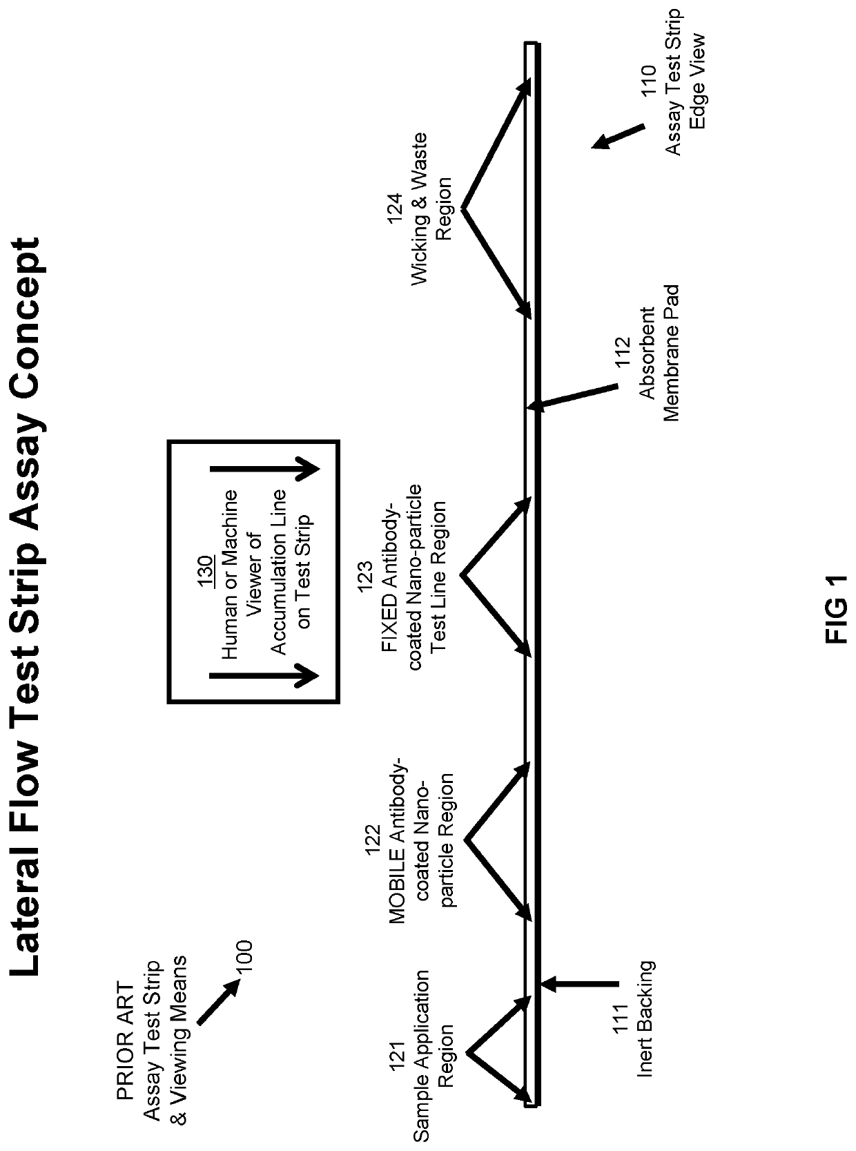
[0048]FIG. 1 illustrates an example prior art Lateral Flow Assay test strip system 100 used to determine the presence or absence of a chosen substance, also known as the analyte, within a liquid. Said test strip consists of a chemically inert backing 111 that may also provide physical strength and stability, and an attached absorbent membrane 112, whose function is to transport liquids from Sample Application Region 121 to Wicking and Waste Region 124, after passing through Regions 122 and 123 described below.

[0049]Located in Region 122 is a deposition of non-reactive metallic or non-metallic nanopa...


PUM

PropertyMeasurementUnit
concentrationaaaaaaaaaa
transparentaaaaaaaaaa
temperatureaaaaaaaaaa

Abstract

A method, apparatus and system that includes an environmentally controlled accurate and sensitive general purpose lateral flow assay instrument that can be used throughout the world, in homes, and make-shift emergency centers, including while connected to the internet to receive reference Transmission Raman Spectroscopy signature data, and to transmit test results.

Description

CROSS-REFERENCE TO RELATED APPLICATION[0001]Priority is claimed under 37 CFR 1.78 and 35 USC 119(e) to U.S. Provisional Application 63 / 027,323 (XT2005191), filed 19 May 2020, which is incorporated by reference.TECHNICAL FIELD[0002]This disclosure relates generally to instruments that determine the presence and / or quantity of chemical compounds. More specifically, this disclosure pertains to automated assay instruments, such as immunoassay instruments, that use the vertical paper based or lateral flow techniques.BACKGROUND[0003]For many years, the paper-based assay method, including the lateral flow method has been known for its ability to provide handy determination of the presence and concentration of various substances. Although the most familiar applications for the lateral flow assay method are pregnancy tests, the method is used for a significant variety of additional tests and in many industries, especially the medical industry. For medical purposes, paper-based, including lat...

Claims


Application Information

Patent Timeline
Patent Type & Authority Applications(United States)
IPC IPC(8): G01N33/543B01L3/00G01N35/00G01N21/65
CPCG01N33/54386G01N33/54373B01L3/5023G01N35/00029G01N21/65B01L2200/025H04L67/10B01L2300/0663B01L2300/126B01L2300/023G01N2035/00108G01N2035/00306B01L2200/04G01N2035/00346G01N2035/00455G01N21/8483G01N21/658B01L3/502715H04L67/12
Inventor SARHAN, SAMEH
Owner XTRAVA INC
Learn More