Supercharge Your Innovation With Domain-Expert AI Agents!

Method and system for removing dust from exhaust gas of engine

a technology of exhaust gas and dust removal system, which is applied in the direction of machines/engines, electric supply techniques, separation processes, etc., can solve the problems of affecting the performance and fuel consumption of the engine, the dedusting effect of a dpf is unstable, and fails to meet the latest filtering requirements, so as to improve the ionization dedusting effect and reduce the effect of electric field coupling

Pending Publication Date: 2021-12-02
SHANGHAI BIXIUFU ENTERPRISE MANAGEMENT CO LTD
View PDF0 Cites 0 Cited by
  • Summary
  • Abstract
  • Description
  • Claims
  • Application Information

AI Technical Summary

Benefits of technology

The present invention provides an engine exhaust gas dedusting system and method using an exhaust gas electric field device. The system can effectively remove particulate matter from the engine exhaust gas. Dust accumulation on the exhaust insulation mechanism and cathode supporting plate can be reduced by using an electric field back corona discharge phenomenon to generate plasmas which break polymer bonds to form small molecular carbon dioxide and water, thus completing the carbon black cleaning treatment. The electric field device includes an exhaust gas dedusting system entrance, an exhaust gas dedusting system exit, and an exhaust gas electric field device. The system has excellent sedimentation effect and can effectively clean the engine exhaust gas. The invention also includes a method to select optimal parameters for the exhaust gas dedusting electric field anode and cathode to reduce the coupling time of the electric field.

Problems solved by technology

(1) Regeneration is needed when a DPF captures a certain amount of particulates. Otherwise, the engine exhaust backpressure will rise and the working state will deteriorate, seriously affecting performance and oil consumption and even blocking the DPF, which can cause engine failure. Thus, a DPF needs to be maintained regularly, and a catalyst needs to be added to it. Even with regular maintenance, the accumulation of particulates restricts an exhaust flow. As a result, the backpressure is increased, affecting the performance and fuel consumption of the engine.
(2) The dedusting effect of a DPF is unstable and fails to meet the latest filtering requirements of engine exhaust gas treatment.
In the prior art, due to problems including large space requirements, a complex system structure, and a poor dedusting effect (In particular under the condition in which the water droplets are contained in high or low temperature exhaust gas, the dedusting efficiency is significantly reduced) and other problems, particulates in engine gas intake cannot be treated by electrostatic dedusting.

Method used


Image

  • Method and system for removing dust from exhaust gas of engine
  • Method and system for removing dust from exhaust gas of engine
  • Method and system for removing dust from exhaust gas of engine

Examples


embodiment 1

[0464]An engine exhaust gas dedusting system of the present embodiment includes exhaust gas treatment system which is configured to treat an exhaust gas to be emitted into the atmosphere.

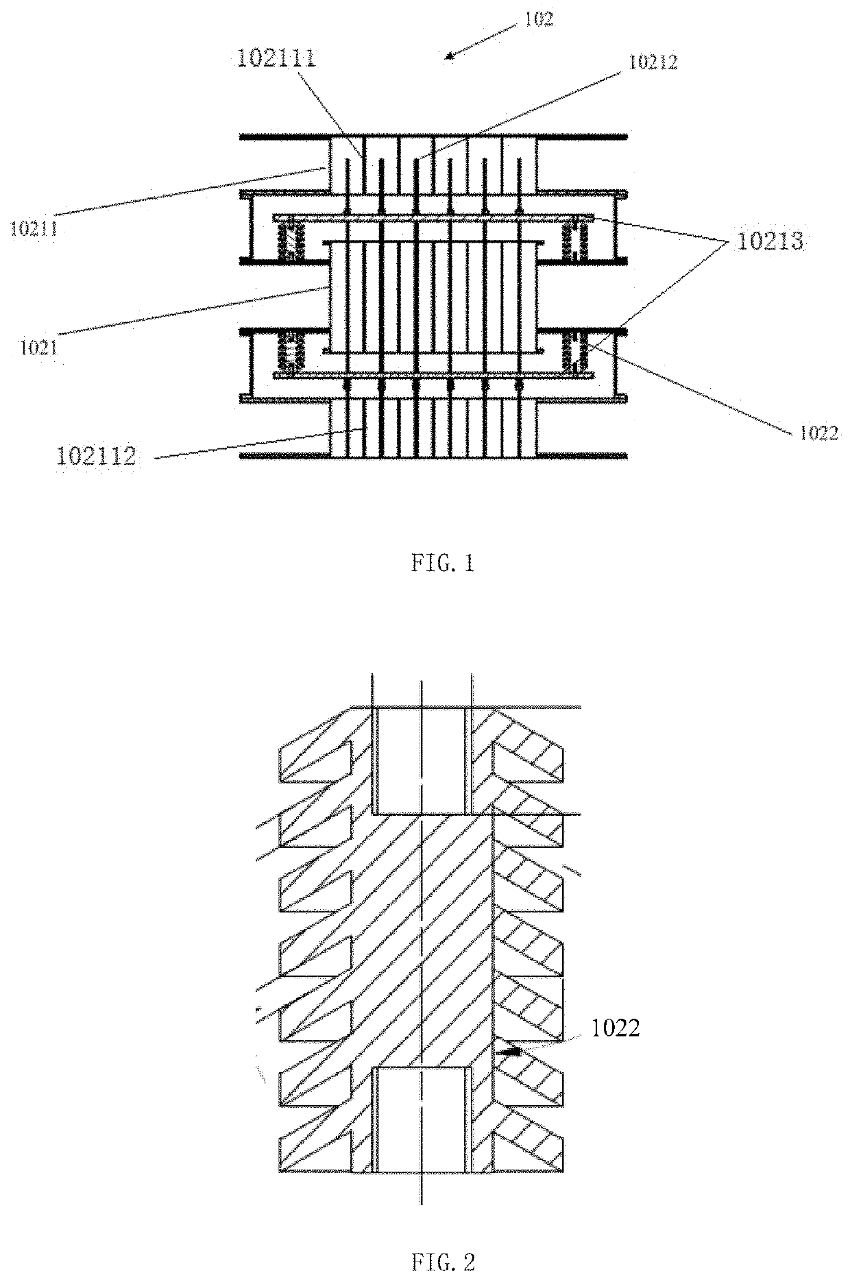
[0465]FIG. 1 shows a structural schematic diagram of an embodiment of an exhaust gas treatment device. As shown in FIG. 1, the exhaust gas treatment device 102 includes an exhaust gas electric field device 1021, an exhaust insulation mechanism 1022, an exhaust gas equalizing device, an exhaust gas water filtering mechanism, an exhaust gas ozone mechanism and an oxygen supplementing device.

[0466]The exhaust gas electric field device 1021 includes an exhaust gas dedusting electric field anode 10211 and an exhaust gas dedusting electric field cathode 10212 provided inside the exhaust gas dedusting electric field anode 10211. An asymmetric electrostatic field is formed between the exhaust gas dedusting electric field anode 10211 and the exhaust gas dedusting electric field cathode 10212. After a gas con...

embodiment 2

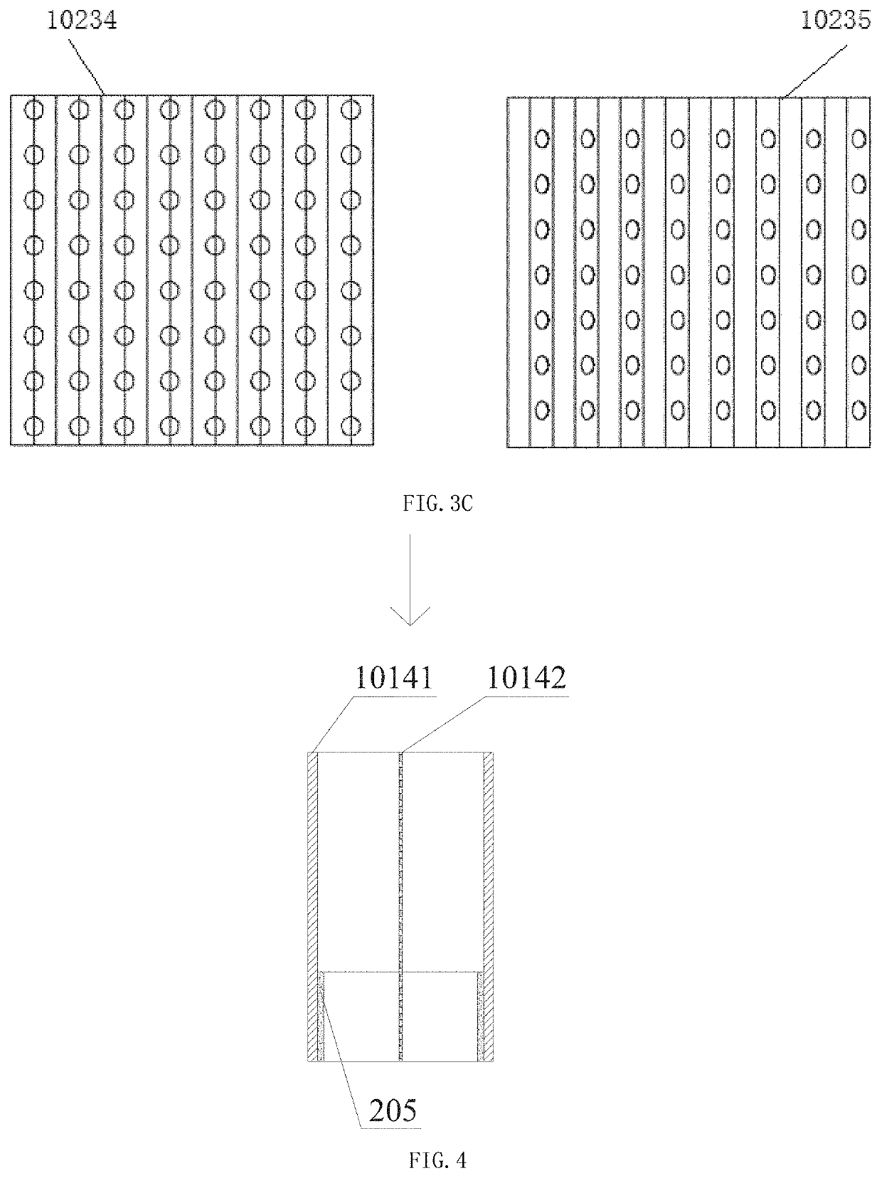
[0481]An exhaust gas electric field device shown in FIG. 4 includes an exhaust gas dedusting electric field anode 10141, an exhaust gas dedusting electric field cathode 10142, and an exhaust gas electret element 205. An exhaust gas ionization dedusting electric field is formed when the exhaust gas dedusting electric field anode 10141 and the exhaust gas dedusting electric field cathode 10142 are connected to a power supply. The exhaust gas electret element 205 is provided in the exhaust gas ionization dedusting electric field. The arrow in FIG. 4 shows the flow direction of a substance to be treated. The exhaust gas electret element 205 is provided at an exhaust gas electric field device exit. The exhaust gas ionization dedusting electric field charges the exhaust gas electret element. The exhaust gas electret element has a porous structure, and the material of the exhaust gas electret element is alumina. The exhaust gas dedusting electric field anode has a tubular interior, the exh...

embodiment 3

[0487]An exhaust gas electric field device shown in FIG. 5 and FIG. 6 includes an exhaust gas dedusting electric field anode 10141, an exhaust gas dedusting electric field cathode 10142, and an exhaust gas electret element 205. The exhaust gas dedusting electric field anode 10141 and the exhaust gas dedusting electric field cathode 10142 form an exhaust gas flow channel 292, and the exhaust gas electret element 205 is provided in the exhaust gas flow channel 292. The arrow in FIG. 5 shows the flow direction of a substance to be treated. The exhaust gas flow channel 292 includes an exhaust gas flow channel exit, and the exhaust gas electret element 205 is close to an exhaust gas flow channel exit. The cross section of the exhaust gas electret element 205 in the exhaust gas flow channel occupies 10% of the cross section of the exhaust gas flow channel, as shown in FIG. 7, which is S2 / (S1+S2)100%, where a first cross sectional area S2 is the cross sectional area of the exhaust gas elec...


PUM


Abstract

A system for removing dust from exhaust gas of an engine, comprising an exhaust gas electric field apparatus and an oxygen replenishment apparatus. The exhaust gas electric field apparatus comprises an exhaust gas electric field apparatus inlet, an exhaust gas electric field apparatus outlet, an exhaust gas dust-removing electric field cathode and an exhaust gas dust-removing electric field anode. The exhaust gas dust-removing electric field cathode and the exhaust gas dust-removing electric field anode are used to generate an ionizing electric field for removing dust from exhaust gas. The oxygen replenishment apparatus is used to add an oxygen-containing gas to the exhaust gas before applying an ionizing electric field for dust removal thereto. The system for removing dust from exhaust gas of an engine has the advantageous effect of dust removal and can effectively remove particulates in exhaust gas of an engine.

Description

TECHNICAL FIELD[0001]The present invention belongs to the field of environmental protection, and it relates to an engine exhaust gas dedusting system and method.BACKGROUND ART[0002]There are a lot of particulates in engine exhaust, so it is necessary to filter the particulates in engine exhaust gas.[0003]In the prior art, particulates are usually filtered by a diesel particulate filter (DPF). A DPF works in a combustion mode. Namely, after a porous structure is sufficiently blocked by carbon deposits and the temperature is raised up to an ignition point, natural combustion or supported combustion is carried out. Specifically, the working principle of a DPF is as follows. A gas intake containing particulates enters a honeycomb-shaped carrier of a DPF, the particulates are trapped in the honeycomb-shaped carrier, and most of the particulates have been filtered out when the gas intake flows out of the DPF. The carrier of a DPF is mainly made of cordierite, silicon carbide, aluminum tit...

Claims


Application Information

Patent Timeline
Patent Type & Authority Applications(United States)
IPC IPC(8): F01N3/01
CPCF01N3/01F01N2240/38B03C3/49B01D53/92B01D53/26B01D53/32Y02T10/12B03C3/01B03C3/014B03C3/0175B03C3/41B03C3/86B03C2201/30F01N2240/04F01N3/005B03C3/06B03C3/66B03C3/885B03C2201/08F01N3/0205F01N3/05F01N5/02F01N5/04F01N13/14F01N13/1805H02K7/1823B03C3/38B03C2201/06F01N2470/20B03C3/28B03C3/70B03C3/74
Inventor TANG, WANFUDUAN, ZHIJUNZOU, YONGANXI, YONG
Owner SHANGHAI BIXIUFU ENTERPRISE MANAGEMENT CO LTD
Features
  • R&D
  • Intellectual Property
  • Life Sciences
  • Materials
  • Tech Scout
  • Unparalleled Data Quality
  • Higher Quality Content
  • 60% Fewer Hallucinations
Learn More