Unlock instant, AI-driven research and patent intelligence for your innovation.

Vapor chamber devices and methods of dissipating heat therewith

Pending Publication Date: 2021-12-02
PURDUE RES FOUND INC
View PDF0 Cites 2 Cited by
  • Summary
  • Abstract
  • Description
  • Claims
  • Application Information

AI Technical Summary

Benefits of technology

The patent describes vapor chamber devices and a method that use two subunits for bulk heat spreading and damping high heat fluxes. These devices offer better performance with lower thermal resistance compared to traditional solid copper heat spreaders and vapor chambers. The technical effect is a reduction in conduction resistance across the internal wick structure, leading to improved heat transfer.

Problems solved by technology

As a nonlimiting example, when applied to thermal management of electronic devices, vapor chamber devices can be subjected to non-uniform power maps that include hotspots (discrete areas with high heat fluxes).
In a conventional vapor chamber device having a single vapor core, there is a design tradeoff between increased power handling (via increased liquid feeding) and reduced conduction thermal resistance.
However, previous evaporator wicks and vapor chamber designs have not been developed or demonstrated with the goal of simultaneously managing both high total powers (over large areas) and randomly located hotspots, despite the importance and prevalence of this power map.

Method used


Image

  • Vapor chamber devices and methods of dissipating heat therewith
  • Vapor chamber devices and methods of dissipating heat therewith
  • Vapor chamber devices and methods of dissipating heat therewith

Examples


Embodiment Construction

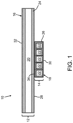
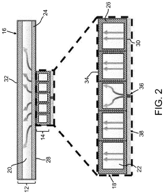
[0023]Existing vapor chamber device designs generally lack the capability of efficiently managing power maps in which both high total powers (over large areas) and small hotpots appear simultaneously. To address, disclosed herein are vapor chamber devices capable of spreading heat from sources that may generate large total heat loads and / or high-power-density hotspots. According to certain nonlimiting aspects of the invention, such vapor chamber devices include a cascaded multi-core unit that includes at least two tiers of cascaded vapor cores, with a top-tier subunit having a vapor core for bulk heat spreading and a bottom-tier subunit with multiple vapor cores for damping of local hotspots that may be generated anywhere over a footprint area thereof.

[0024]FIG. 1 represents a nonlimiting vapor chamber device 10 that includes a cascaded multi-core unit having a top-tier subunit 12 and a bottom-tier subunit 14. The top-tier subunit 12 includes a first housing 16 having walls that enc...


PUM


Abstract

A vapor chamber device having a first vapor core configured to passively spread heat from a localized first input area to a relatively larger first output area adjacent to and in thermal contact with a heat output side of the vapor chamber device, and a second vapor core configured to passively spread heat from a localized second input area adjacent to and in thermal contact with a heat input side of the vapor chamber device to a relatively larger second output area in thermal contact with the first input area of the first vapor core. The second vapor core is configured to attenuate high heat flux hotspots on the first input area before the heat fluxes thereof pass through the second output area of the second vapor core to the first input area of the first vapor core.

Description

CROSS REFERENCE TO RELATED APPLICATIONS[0001]This application claims the benefit of U.S. Provisional Application No. 63 / 030,064 filed May 26, 2020, the contents of which are incorporated herein by reference.BACKGROUND OF THE INVENTION[0002]The present invention generally relates to thermal management processes and equipment. The invention particularly relates to vapor chamber devices capable of spreading heat, including heat from sources that generate large total heat loads and / or high-power-density hotspots.[0003]Vapor chamber devices have long been used in thermal management applications. Such devices passively spread heat from a localized input area to a relatively larger output area, where the heat can then be rejected, as nonlimiting examples, to a heat sink or cold plate. As a nonlimiting example, when applied to thermal management of electronic devices, vapor chamber devices can be subjected to non-uniform power maps that include hotspots (discrete areas with high heat fluxes...

Claims


Application Information

Patent Timeline
IPC IPC(8): F28D15/02F28D15/04
CPCF28D15/0266F28D15/04F28D15/0275
Inventor BANDYOPADHYAY, SOUMYAMARCONNET, AMY MARIEWEIBEL, JUSTIN A.
Owner PURDUE RES FOUND INC