
Ultrasound control unit

Pending Publication Date: 2021-12-09
KONINKLJIJKE PHILIPS NV
View PDF0 Cites 0 Cited by
  • Summary
  • Abstract
  • Description
  • Claims
  • Application Information

AI Technical Summary

Benefits of technology

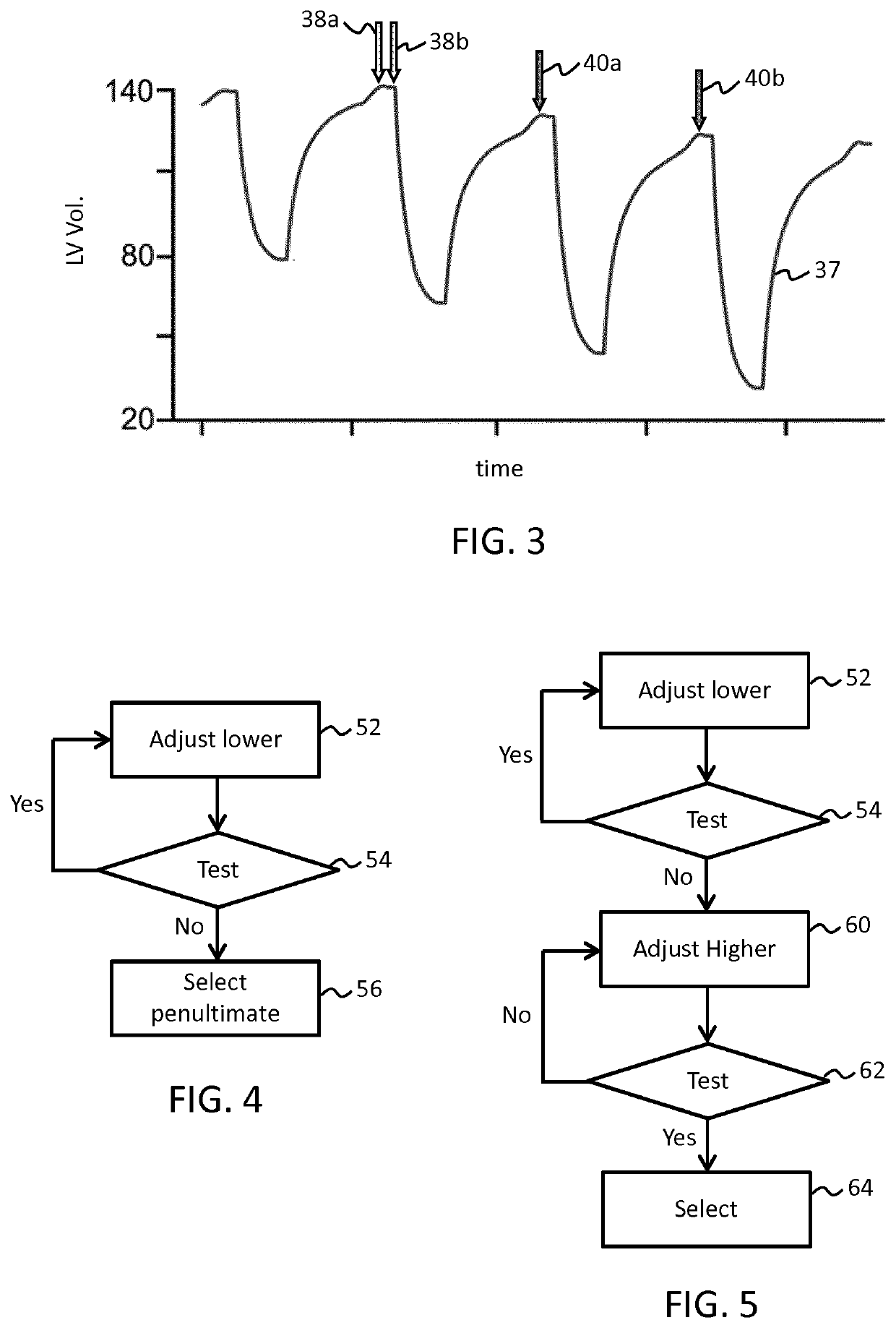
The patent describes a ultrasound system that can collect data with reduced quality to determine its reliability for use in determining physiological parameters of interest. The system switches to a lower power setting mode only after the reliability test meets a minimum condition. Additionally, the system includes a mechanism for acquiring data at a high step rate to ensure fair comparison between data collected at different steps. The system can also switch to a high-power setting for more precise measurements based on certain threshold levels for one or more vital signs. The technical effects of this patent include reducing power output to allow for ultrasound imaging over long periods while still retaining robust parameter quantification based on derived images, achieving better anatomical pictures with a relatively high step rate, and optimizing power management with a defined high-power setting.

Problems solved by technology

The latter is becoming increasingly unpopular with clinicians due to its invasive nature.
Conventional ultrasound imaging solutions are not designed for long term monitoring.
A common problem is overheating of the ultrasound transducer when operated for the extended periods required for continuous monitoring.
Overheating causes conventional ultrasound devices either to fail or to automatically enter cool-down cycles to limit probe or tissue heating.
Intermittent shut-down periods are not clinically acceptable.
Further to this, in some applications, such as mobile systems, available power is in general limited, for example if an ultrasound transducer unit is battery powered or supplied by low-power sources such as a USB output.
Continuous monitoring in these cases quickly drains available power, or even overloads the limited power supply.

Method used


Image

  • Ultrasound control unit
  • Ultrasound control unit
  • Ultrasound control unit

Examples


Embodiment Construction

[0084]The invention will be described with reference to the Figures.

[0085]It should be understood that the detailed description and specific examples, while indicating exemplary embodiments of the apparatus, systems and methods, are intended for purposes of illustration only and are not intended to limit the scope of the invention. These and other features, aspects, and advantages of the apparatus, systems and methods of the present invention will become better understood from the following description, appended claims, and accompanying drawings. It should be understood that the Figures are merely schematic and are not drawn to scale. It should also be understood that the same reference numerals are used throughout the Figures to indicate the same or similar parts.

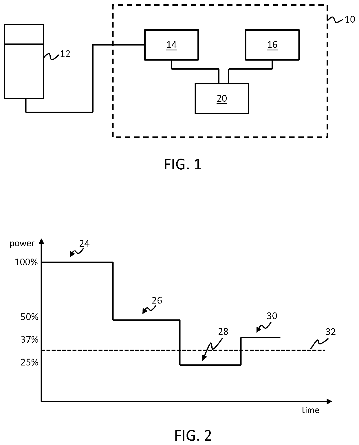
[0086]The invention provides an ultrasound control unit for coupling with an ultrasound transducer unit. The control unit is adapted to control a drive configuration or setting of the transducers of the transducer unit, ea...


PUM


Abstract

An ultrasound control unit (10) is for coupling with an ultrasound transducer unit (12). The control unit is adapted to control a drive configuration or setting of the transducers of the transducer unit, each drive setting having a known power consumption level associated with it. The control unit includes a control module (20) adapted to adjust the drive setting from a first setting to a second setting, the second having a lower associated power consumption that the first. The second setting is tested by an analysis module (16), the analysis module adapted to determine a measure of reliability of ultrasound data acquired by the transducer unit, for the purpose of deriving at least one physiological parameter, when configured in the second setting. The second setting is only used if its determined reliability passes a pre-defined reliability condition.

Description

FIELD OF THE INVENTION[0001]This invention relates to an ultrasound control unit for controlling an ultrasound transducer unit, and in particular for managing a drive setting of the transducer unit.BACKGROUND OF THE INVENTION[0002]Ultrasound imaging is a widespread modality used to diagnose various cardiac conditions.[0003]Recent advancements in image processing algorithms and transducer development have enabled continuous monitoring applications. Many new clinical insights can be gained from continuous monitoring as compared to a single scan. It also offers benefits over other monitoring techniques due to its non-invasiveness, absence of risk of infection, and absence of any ionizing radiation.[0004]Ultrasound acquisition may be coupled with intelligent image analysis and signal processing algorithms for example. Such systems are becoming a valuable tool for patient monitoring at the point-of-care.[0005]One particularly valuable application for continuous ultrasound monitoring may ...

Claims


Application Information

Patent Timeline
IPC IPC(8): A61B8/00
CPCA61B8/546A61B8/58A61B8/56A61B8/5223A61B8/5292A61B8/54A61B8/585
Inventor SUTTON, JONATHAN THOMASGROTH, ALEXANDERWEBER, FRANK MICHAELBHARAT, SHYAMBINGLEY, PETERRAJU, BALASUNDAR IYYAVU
Owner KONINKLJIJKE PHILIPS NV
Learn More