High-performance, energy-saving, automatic cooper-melting apparatus

a cooper-melting apparatus and high-performance technology, applied in the field of preparation of cupric sulfate, can solve the problems of poor copper-melting efficiency, high data delay, high energy consumption, etc., and achieve the effect of high performance and simple structur

Pending Publication Date: 2021-12-16
JIANGXI XINBORUI TECH CO LTD
View PDF0 Cites 2 Cited by
  • Summary
  • Abstract
  • Description
  • Claims
  • Application Information

AI Technical Summary

Benefits of technology

[0013]The disclosed apparatus implements gas-liquid opposite ejection to enable even distribution of oxygen and features a simple structure and high performance as evidenced by its 400 kg / h copper-melting capacity. The disclosed apparatus leverages the 90° C.-120° C. hot air generated by the 20000 rpm rotation of the air suspension blower to heat the solution, thereby eliminating the need for an additional electric or steam boiler and in turn saving an equipment investment equal to about USD 70,000 and a power bill of USD 2,600 per day. In addition, the disclosed apparatus replaces manual adjustment with automation, thereby achieving consistent production and smart-factory practice.

Problems solved by technology

However, the prior-art devices for making copper salts are diverse, and tend to suffer from uneven air supply, poor copper-melting efficiency, high energy consumption, high data delay, high process variation, and low automation, thus being unfavorable to consistent, efficient and energy-saving production.

Method used


Image

  • High-performance, energy-saving, automatic cooper-melting apparatus
  • High-performance, energy-saving, automatic cooper-melting apparatus
  • High-performance, energy-saving, automatic cooper-melting apparatus

Examples


Embodiment Construction

[0017]The following description is to be read in conjunction with the accompany drawings to illustrate the technical schemes of embodiments of the present invention in detail. It is apparent that the described embodiments are merely exemplary, but not exhaustive. All other embodiments obtained by people of ordinary in the art based on embodiments of the present invention without creative efforts are within the scope of the present invention.

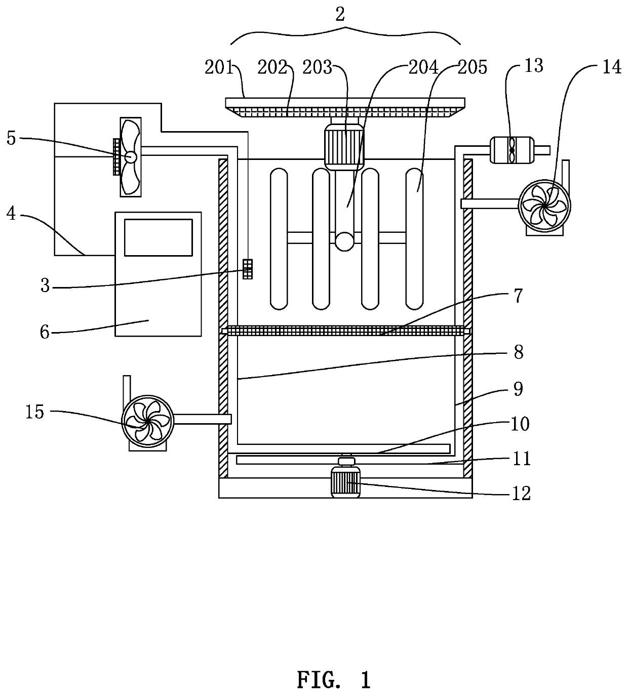
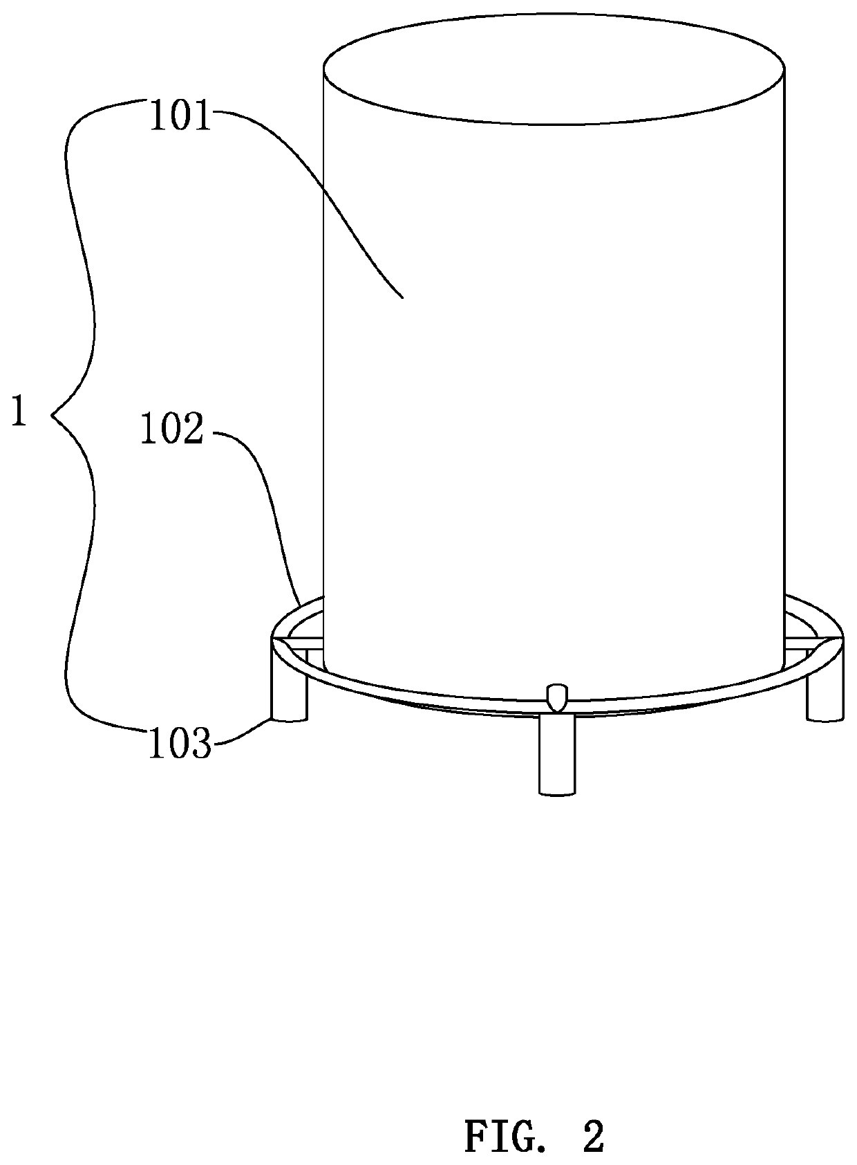
[0018]Referring to FIG. 1-3, the present invention provides technical schemes as described below. The disclosed high-performance, energy-saving, automatic cooper-melting apparatus comprises peripherals 1 that contain a tank 101 acting as a main body. The tank 101 has a bottom peripherally installed with a foundation 102 whose bottom is provided with supports 103.

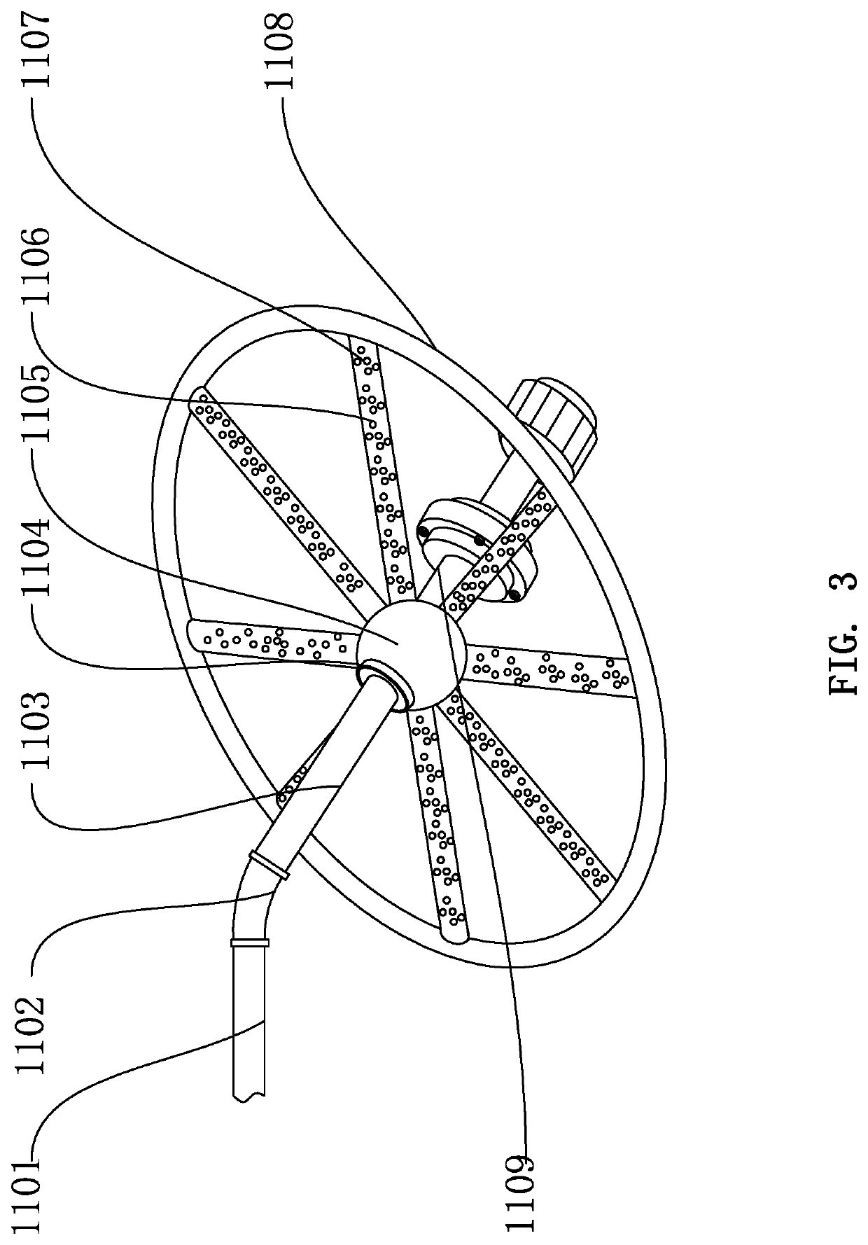
[0019]For better stirring cooper blocks fed thereinto, the disclosed apparatus is equipped with stirrers. Specifically, the tank 101 has a top capped by an upper stirring device 2. The up...


PUM

PropertyMeasurementUnit
diameteraaaaaaaaaa
temperatureaaaaaaaaaa

Abstract

A high-performance, energy-saving, automatic cooper-melting apparatus, includes peripherals containing a tank acting as a main body. The tank has a top capped by an upper stirring device that has a top equipped with a lid. The lid has a lower surface with a sealing pad attached thereto. The sealing pad is centrally installed with a stirring motor. The stirring motor is centrally installed with a post. The post is equipped peripherally with stirring rollers. The tank contains a probe connected to an electric cord whose two ends are connected to an air suspension blower and a DCS detecting device, respectively. The tank contains a screen plate. The tank has one lateral provided with an air pipe and an opposite lateral provided with a liquid pipe. The air pipe has one end fixed with an air pipe stirrer, and the liquid pipe has one end fixed with a liquid pipe stirrer.

Description

BACKGROUND OF THE INVENTION1. Technical Field[0001]The present invention relates to preparation of cupric sulfate, and more particularly to a high-performance, energy-saving, automatic cooper-melting apparatus.2. Description of Related Art[0002]The process of making CuSO4 from copper wire or electrolytic copper blocks with the presence of sulfuric acid necessitates air, water, copper mass, and temperature and can be expressed by the reaction formula below:[0003]In this process, air acts as the source of oxygen and is therefore of high importance. Copper first reacts with oxygen and undergoes oxidation. The resulting CuO then reacts with sulfuric acid to generate CuSO4. The faster copper gets oxidized, the faster CuSO4 is generated. Oxygen is supplied through the air pipe and the liquid pipe equipped at the bottom of the copper melting tank. The more plentiful and even O2 is in the supplied liquid, the faster copper melts. Gas-liquid opposite ejection allows oxygen to be well mixed w...

Claims


Application Information

Patent Timeline
Patent Type & Authority Applications(United States)
IPC IPC(8): F27B15/10B01F3/04B01F27/96
CPCF27B15/10C01G3/10B01F3/04539B01J19/18B01J19/0053B01J19/0006B01J19/0013B01J4/001B01J4/002B01J4/004B01J4/008B01J19/0066B01J2204/002B01J2204/005B01J2219/00123Y02P20/10Y02P20/141B01F2101/45B01F35/91B01F33/86B01F27/07261B01F35/45B01F25/4523B01F23/23314B01J19/0073C01G1/10B01F23/2331B01F23/237612
Inventor CHEN, XIAODONGCHEN, ZERENHUANG, GUOHE
Owner JIANGXI XINBORUI TECH CO LTD
Why Eureka
Try Eureka