Shielded busbar

a busbar and shielding technology, applied in the field of shielding busbars, can solve the problems of poor mitigating effect, complex adapting work, poor effect, etc., and achieve the effect of improving the effectiveness of magnetic shielding and being easy to manufactur

Active Publication Date: 2021-12-16
BESHIELDING SRL
View PDF0 Cites 0 Cited by
  • Summary
  • Abstract
  • Description
  • Claims
  • Application Information

AI Technical Summary

Benefits of technology

[0010]The object of the present invention is to overcome the drawbacks mentioned above by providing a shielding fo

Problems solved by technology

However, often lower magnetic induction values may be required at such a distance, for example 0.2-0.1 (μT), especially when the busbars installed in environments where electronic equipment is present.
This solution also requires a complex work of adapting said outer shielding to the outer casing of the busbars, sometimes carried out by specialised technician

Method used


Image

  • Shielded busbar
  • Shielded busbar
  • Shielded busbar

Examples


Embodiment Construction

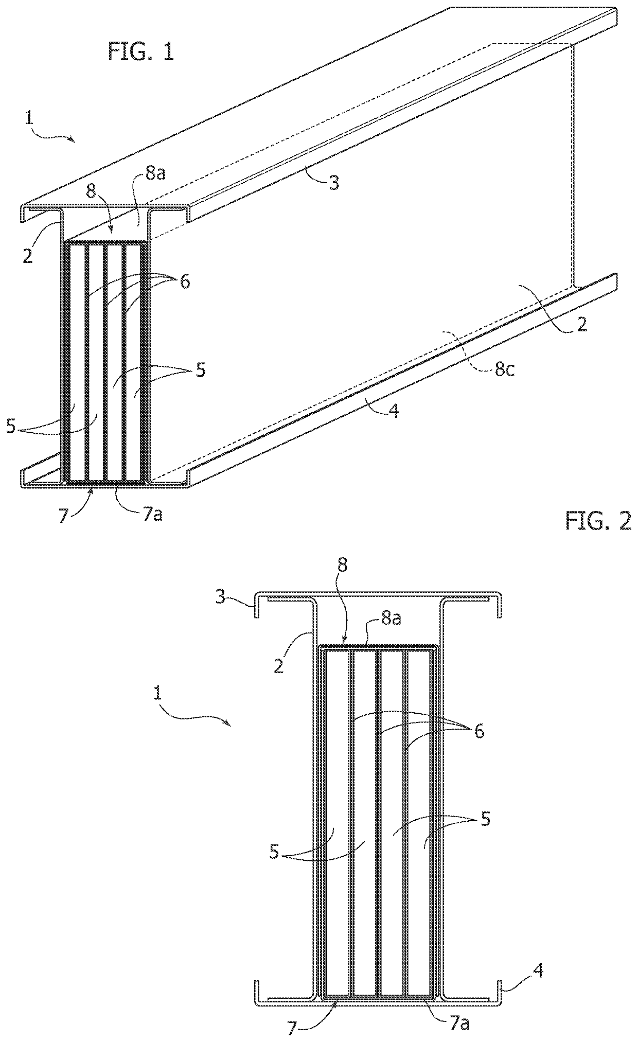
[0027]Initially with reference to FIG. 1, a busbar comprising an outer support casing 2 in the form of an elongated parallelepiped and provided, at the smaller lateral faces thereof, with an upper flange 3 and a lower flange 4 is indicated with 1. Arranged inside the casing 2 is a plurality of conductor bars 5 with a flattened rectangular-shaped cross-section, arranged parallel to each other along the longitudinal direction of the casing 2 so that the larger lateral surfaces of the adjacent conductor bars face each other. Provided for in the example illustrated in the figures are four conductor bars 5 according to a typical arrangement of the three-phase conductors (three phase conductors and one neutral conductor). It is clear that the number of conductor bars may vary depending on the applications.

[0028]As better observable in FIG. 2, the larger and smaller lateral faces of each conductor bar 5 are at contact with a coating made of insulating material 6.

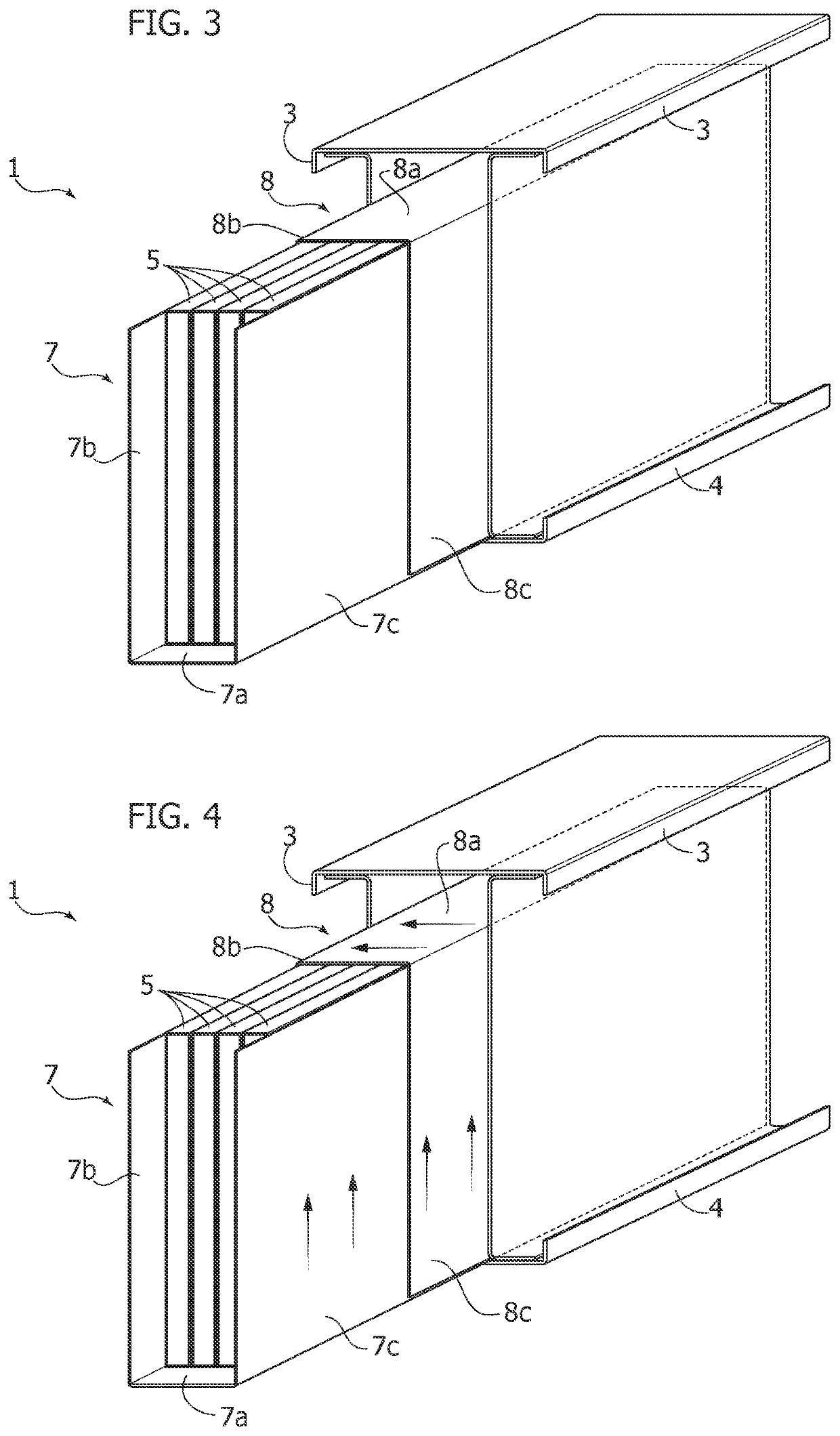
[0029]With reference to FIG...


PUM


Abstract

A busbar having a magnetic shielding structure arranged between conductor bars and an outer casing. The magnetic shielding structure includes a first shielding element and a second shielding element each having a U-shaped cross-section. The shielding elements are made of ferromagnetic material and enclose—on opposite sides—conductor bars so that each fin of the first shielding element is at least partially superimposed on a homologous fin of the second shielding element. The shielding elements can consist of anisotropic ferromagnetic strips with oriented grains.

Description

FIELD OF THE INVENTION[0001]The present invention regards systems for the transportation and distribution of electrical energy and more particularly it regards busbars.STATE OF THE PRIOR ART[0002]The busbars are prefabricated electric bars consisting of modular structures comprising conductor elements, normally in the form of rigid bars made of conductive material, typically copper or aluminium, in a support casing made of conductive or ferromagnetic or combined material, which also serves the function of thermal dissipation of the heat produced due to the Joule effect by such conductor bars and sometimes even a first containment of the emitted magnetic field.[0003]Busbars are used as an alternative to the use of electric cables, especially in the commercial and industrial field. The busbars can be used for conducting currents of a few tens up to several thousands of amperes, offering some advantages with respect to conventional cables such as, for example, modularity, ease of insta...

Claims


Application Information

Patent Timeline
IPC IPC(8): H02G5/06H02G5/00
CPCH02G5/06H02G5/002H02G5/005
Inventor CANOVA, ALDO
Owner BESHIELDING SRL
Why Eureka
Try Eureka