Card connector

a card connector and card technology, applied in the direction of fixed connections, coupling device connections, instruments, etc., can solve the problem of possible induced reciprocal interference, and achieve the effect of suppressing electromagnetic radiation interference, reducing capacitive effect, and improving high frequency performan

Pending Publication Date: 2021-12-23
V GENERAL TECH CO LTD
View PDF4 Cites 1 Cited by
  • Summary
  • Abstract
  • Description
  • Claims
  • Application Information

AI Technical Summary

Benefits of technology

[0026]Based on the above structure, the first differential soldering section and the second differential soldering section, the third differential soldering section and the fourth differential soldering section, and the fifth differential soldering section and the sixth differential soldering section are arranged side by side in a pairwise form, and the second grounding soldering section is arranged between the first and second differential soldering sections and the third and fourth differential soldering sections; and the fourth grounding soldering section and the fifth grounding soldering section are arranged between the third and fourth differential soldering sections and the fifth and sixth differential soldering sections, so that capacitive effect can be reduced and thus bettering of the high frequency performance and suppressing of electromagnetic radiation interference can be realized.

Problems solved by technology

Due to such a large number of terminals, mutual interference may be quite possibly induced between the terminals, and a capacitive effect may be generated.

Method used


Image

  • Card connector
  • Card connector
  • Card connector

Examples


Embodiment Construction

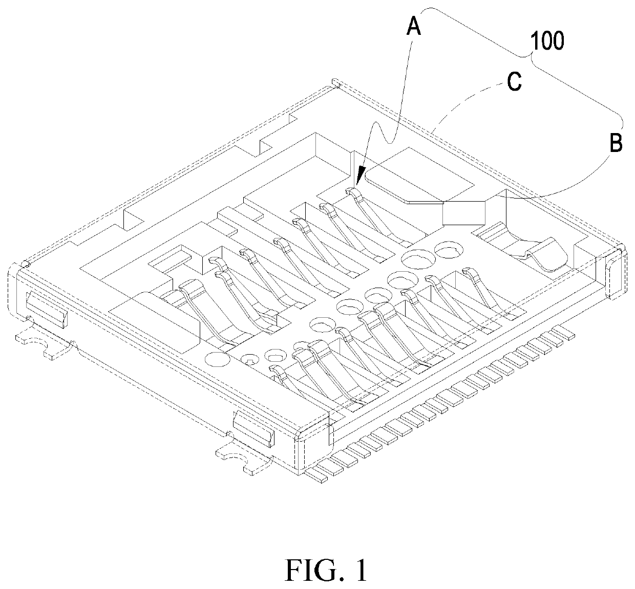
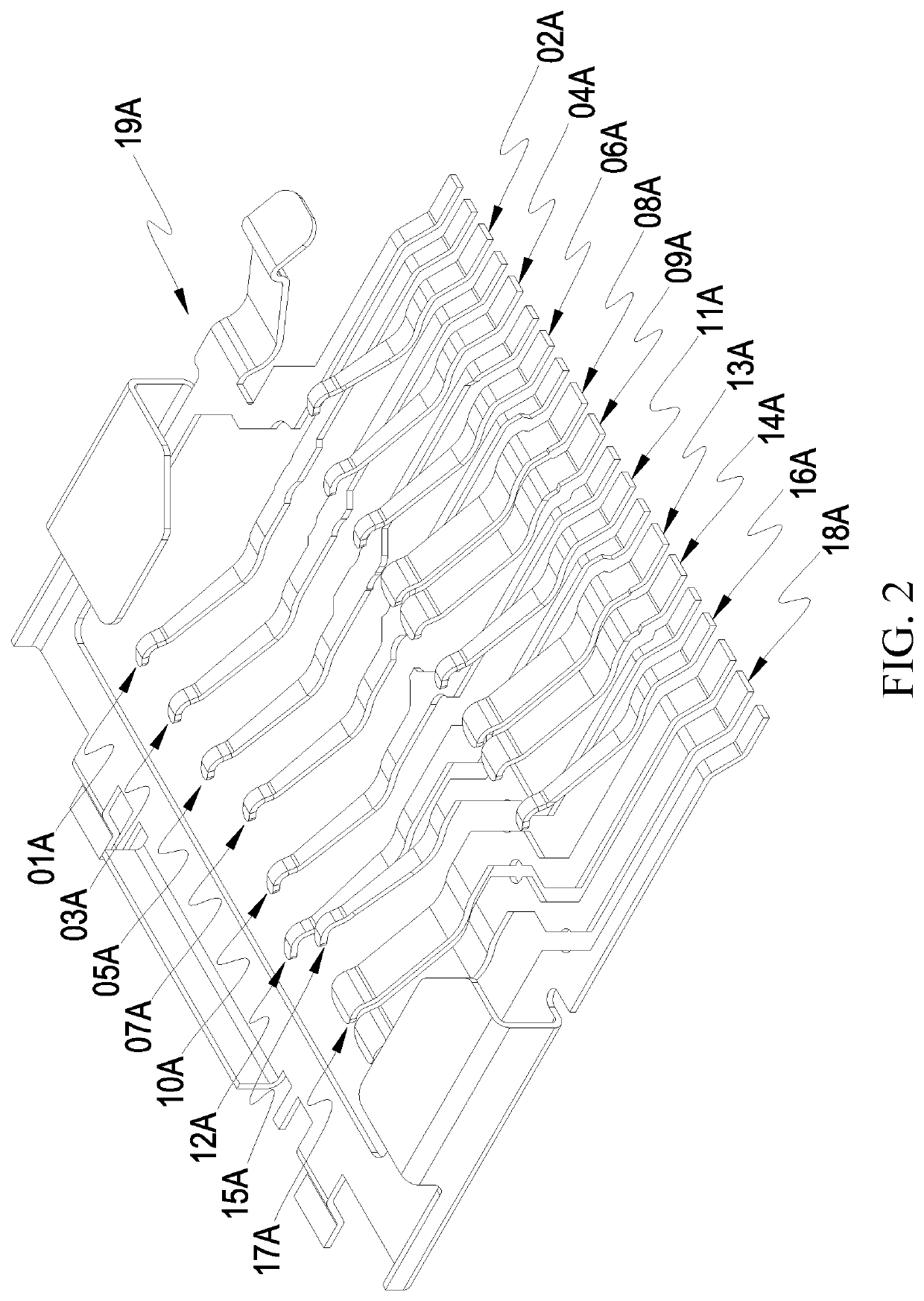
[0034]Referring to FIGS. 1-7, the drawings clearly show the present invention provides a card connector 100. The card connector 100 comprises a transmission conductor assembly A, an insulative plastic body B arranged outside the transmission conductor assembly A, and a shielding case C arranged outside the insulative plastic body B. The transmission conductor assembly A is arranged to meet the specification of microSD. The transmission conductor assembly A comprises:

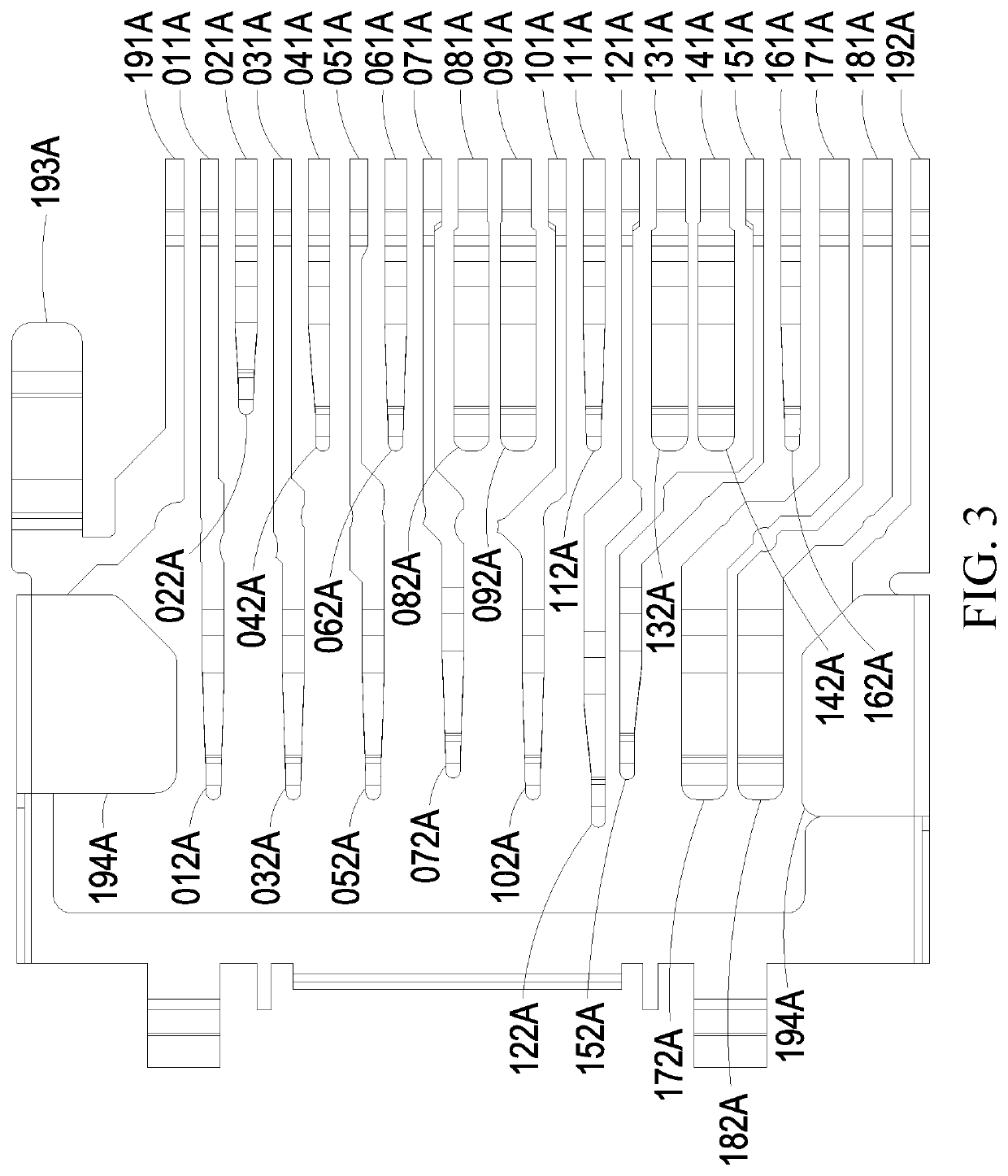
[0035]a first signal transmission conductor 01A, wherein the first signal transmission conductor 01A has two ends that are extended to respectively form a first signal soldering section 011A and a first signal spring section 012A;

[0036]a first power transmission conductor 02A, wherein the first power transmission conductor 02A has two ends that are extended to respectively form a first power soldering section 021A and a first power spring section 022A, and the first power soldering section 021A is located at one side of ...


PUM


Abstract

A card connector includes a transmission conductor assembly. The transmission conductor assembly includes a first signal transmission conductor, a first power transmission conductor, an inspection signal transmission conductor, a second signal transmission conductor, a command reset transmission conductor, a first grounding transmission conductor, a second power transmission conductor, a first differential transmission conductor, a second differential transmission conductor, a third signal transmission conductor, a second grounding transmission conductor, a third grounding transmission conductor, a third differential transmission conductor, a fourth differential transmission conductor, a fourth grounding transmission conductor, a fifth grounding transmission conductor, a fifth differential transmission conductor, a sixth differential transmission conductor, and an outside grounding transmission conductor, each of which has a spring section and a soldering section. The soldering sections, being so arranged, achieve advantages of bettering high frequency performance, reducing capacitive effect, and suppressing electromagnetic radiation interference.

Description

TECHNICAL FIELD OF THE INVENTION[0001]The present invention relates to a card connector, and more particularly to a card connector featuring bettered high frequency performance, reduced capacitive effect, and suppressed electromagnetic radiation interference.DESCRIPTION OF THE PRIOR ART[0002]Security Digital, commonly abbreviated as SD, refers to a memory card, which is widely used in portable devices, such as digital cameras, personal digital assistants (PDAs), and multimedia players. SD technology is based on the MultiMediaCard (MMC) format. The SD card has a relatively high data transmission rate and is constantly updating the standards thereof. Most of the SD cards are provided with, on a lateral side thereof, with write protection control to prevent accidental data writing in the card. Some of the SD cards even support digital copyright management technology. The size of the SD cards is generally 32 mm×24 mm×2.1 mm but would be different for different types, such as micro SD. A...

Claims


Application Information

Patent Timeline
Patent Type & Authority Applications(United States)
IPC IPC(8): H01R13/6471H01R4/02H01R13/6585H01R13/514H01R13/15
CPCH01R13/6471H01R4/02H01R13/15H01R13/514H01R13/6585H01R12/57H01R12/714H01R12/716H01R12/73H01R13/6594G06K7/0026G06K7/0082H01R12/727
Inventor YEH, PO-WENCHUNG, HSUAN HOLIN, YUNG-CHANGLIN, YU HUNGYEH, TZU-WEIYEH, YU-LUN
Owner V GENERAL TECH CO LTD
Why Eureka
Try Eureka