
Electro-permanent magnet thermal protection

Active Publication Date: 2021-12-30
DELL PROD LP
View PDF0 Cites 0 Cited by
  • Summary
  • Abstract
  • Description
  • Claims
  • Application Information

AI Technical Summary

Benefits of technology

The present invention provides a system and method for using electro-permanent magnets in increased thermal states while reducing the disadvantages and problems associated with previous methods. The system automatically switches the electro-permanent magnets to an off state when a predetermined thermal state is reached to protect against de-magnetization. This results in increased manufacture efficiency and allows electro-permanent magnets to be incorporated in various information handling system circuit boards. Additionally, thermal condition monitoring helps in protecting against de-magnetization and allows the electro-permanent magnets to return to normal operations when the thermal constraint is resolved, thus preventing electro-permanent magnet failure during normal system operations.

Problems solved by technology

One difficulty with using electro-permanent magnets is their sensitivity to heat, which can cause de-magnetization.
In some instances, hand soldering can be quite inefficient, such as in a keyboard where over 100 electro-permanent magnet components may be used on a single circuit board.
Generally, however, the heat of an oven to couple the components to the circuit board can result in de-magnetization of the electro-permanent magnets.

Method used


Image

  • Electro-permanent magnet thermal protection
  • Electro-permanent magnet thermal protection
  • Electro-permanent magnet thermal protection

Examples


Embodiment Construction

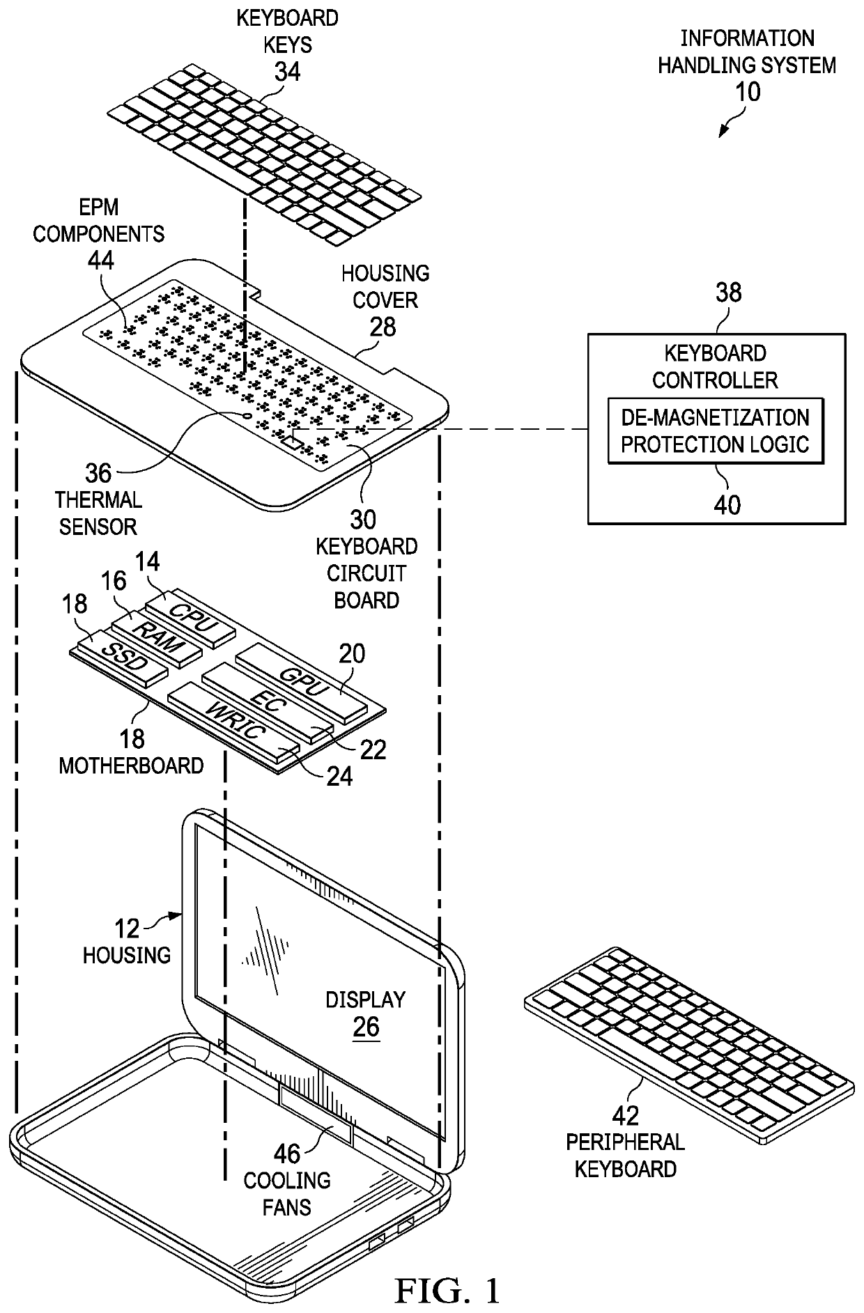
[0015]An electro-permanent magnet associated with an information handling system is protected from de-magnetization by adjusting to an off state during predetermined thermal conditions. For purposes of this disclosure, an information handling system may include any instrumentality or aggregate of instrumentalities operable to compute, classify, process, transmit, receive, retrieve, originate, switch, store, display, manifest, detect, record, reproduce, handle, or utilize any form of information, intelligence, or data for business, scientific, control, or other purposes. For example, an information handling system may be a personal computer, a network storage device, or any other suitable device and may vary in size, shape, performance, functionality, and price. The information handling system may include random access memory (RAM), one or more processing resources such as a central processing unit (CPU) or hardware or software control logic, ROM, and / or other types of nonvolatile me...


PUM


Abstract

De-magnetization protection is provided for electro-permanent magnets during information handling system manufacture and use by monitoring thermal conditions at the information handling systems to detect a thermal state associated with de-magnetization and commanding the electro-permanent magnets to an off state so that both magnets in the electro-permanent magnet have opposing polarities. The opposing polarities tend to stabilize magnet polarity to prevent de-magnetization during increased temperatures. Normal operations are then re-enabled once temperatures decrease.

Description

BACKGROUND OF THE INVENTIONField of the Invention[0001]The present invention relates in general to the field of information handling systems that include electro-permanent magnets, and more particularly to electro-permanent magnet thermal protection.Description of the Related Art[0002]As the value and use of information continues to increase, individuals and businesses seek additional ways to process and store information. One option available to users is information handling systems. An information handling system generally processes, compiles, stores, and / or communicates information or data for business, personal, or other purposes thereby allowing users to take advantage of the value of the information. Because technology and information handling needs and requirements vary between different users or applications, information handling systems may also vary regarding what information is handled, how the information is handled, how much information is processed, stored, or communic...

Claims


Application Information

Patent Timeline
IPC IPC(8): H01F7/06H01F7/18H01H13/785H01F13/00
CPCH01F7/064H01F7/1811H05K7/20136H01F13/006H01H13/785H01F7/04H01F7/00H01H2221/04H01H13/85
Inventor MORRISON, JASON S.CASPARIAN, MARK A.
Owner DELL PROD LP
Features
  • Generate Ideas
  • Intellectual Property
  • Life Sciences
  • Materials
  • Tech Scout
  • Unparalleled Data Quality
  • Higher Quality Content
  • 60% Fewer Hallucinations
Learn More