Permanent magnet multiple-pole switch reluctance motor

A switched reluctance and motor technology, applied in the direction of magnetic circuit rotating parts, electrical components, electromechanical devices, etc., can solve the problems of non-self-starting, increase control cost, increase magnetic energy area, etc., to protect wind abrasion loss, The effect of protecting environmental corrosion and strengthening mechanical strength

Inactive Publication Date: 2014-09-03
张世清
View PDF6 Cites 0 Cited by
  • Summary
  • Abstract
  • Description
  • Claims
  • Application Information

AI Technical Summary

Problems solved by technology

The number of phases is large and the step angle is small, which is conducive to reducing torque ripple, but the structure is complex, and there are many main switching devices, and the cost is high. At present, there are more three-phase 6 / 4 structures, four-phase 8 / 6 structures and three-phase 12 / 8 structure; because there are two-phase 4 / 2 in theory, but products cannot be produced, this is because they cannot start automatically, even if the auxiliary start cannot reach the running torque
The ones larger than three-phase 12 / 8 are three-phase 12 / 10, five-phase 10 / 4, five-phase 10 / 8, seven-phase 14 / 12, etc. These combinations not only increase the number of phases, but also increase the cost of control , which also increases the difficulty of control; and during the commutation process of the motor, only two pairs of magnetic poles per phase enter the work state at most, such as three-phase 12 / 8, especially when it is below 12 / 8, the stator and rotor poles are a pair of magnetic poles to generate magnetic pull ; Another example is four-phase 8 / 4, each phase stator has a pair of magnetic poles, and the rotor has only a pair of magnetic poles, which results in large unilateral magnetic pull, large noise and vibration, and a reduction in the area surrounded by magnetic energy conversion Ψ-i. The reason for the reduction of the magnetic energy area
In practical applications, switched reluctance motors have the disadvantage of not being able to manufacture multiple phases and multiple slots, and the windings can only conduct electricity in one direction in the forward direction, and the windings pass current in one direction. At the same time, there are technical problems that cannot be permanent magnetized
[0003] The invention patent I have applied for is "Permanent Magnet Double-Pole Switched Reluctance Motor Generator" and the application number is 200910220948.7. It is two types of "Permanent Magnet Switched Reluctance Motor Generator". The device is a single-stage two-phase double-stage Four-phase and single-segment three-phase double-segment six-phase "Permanent Magnet Double-Pole Switched Reluctance Motor Generator", and has a high-performance permanent magnet double-pole switched reluctance motor, but the rotor poles are surface-mounted with permanent magnet poles Although the improvement of this patented technology breaks through the problem of the permanent magnet of the traditional switched reluctance motor, and increases the magnetic co-energy area; The manufacturing method and performance need to be further expanded

Method used


Image

  • Permanent magnet multiple-pole switch reluctance motor
  • Permanent magnet multiple-pole switch reluctance motor
  • Permanent magnet multiple-pole switch reluctance motor

Examples


Embodiment Construction

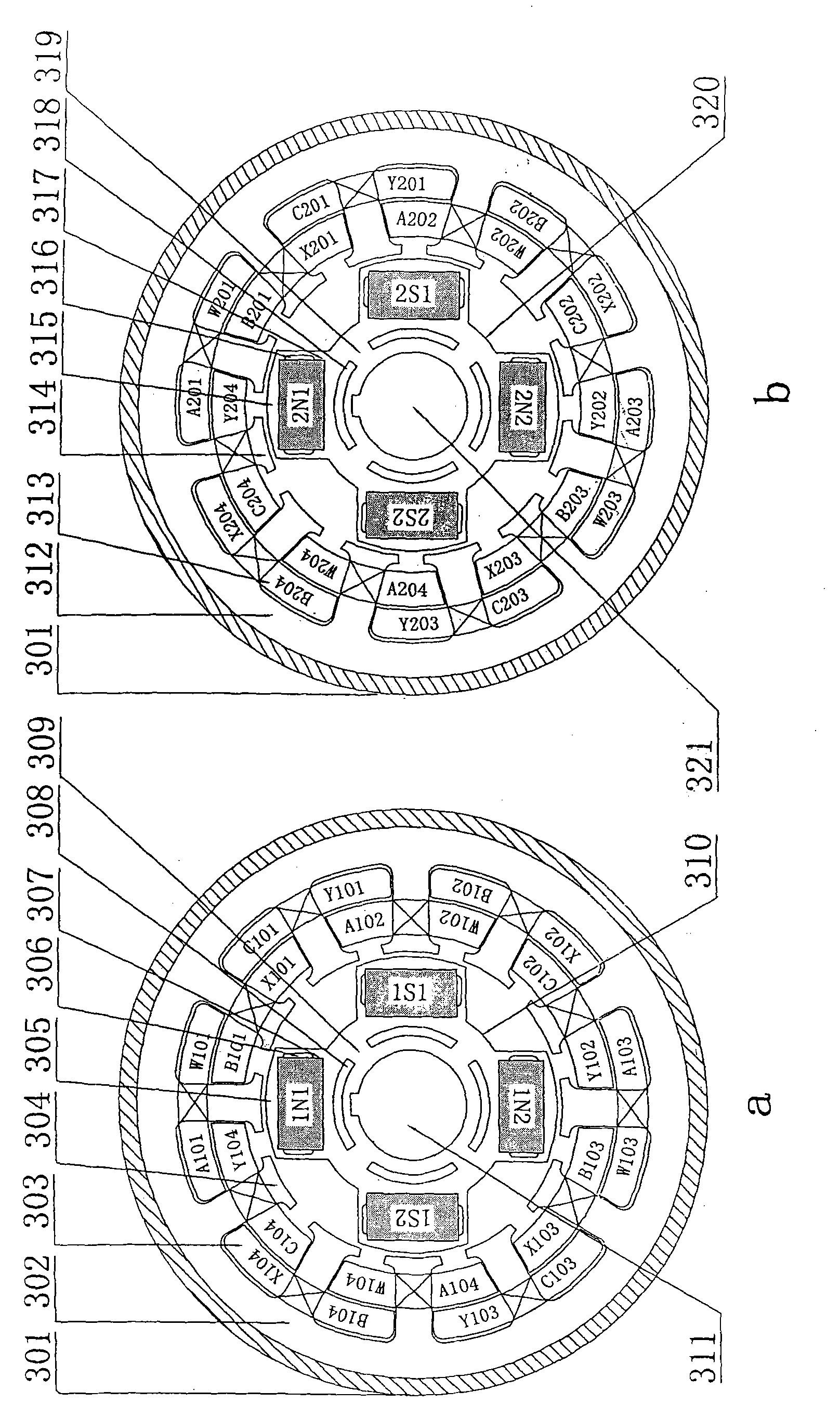
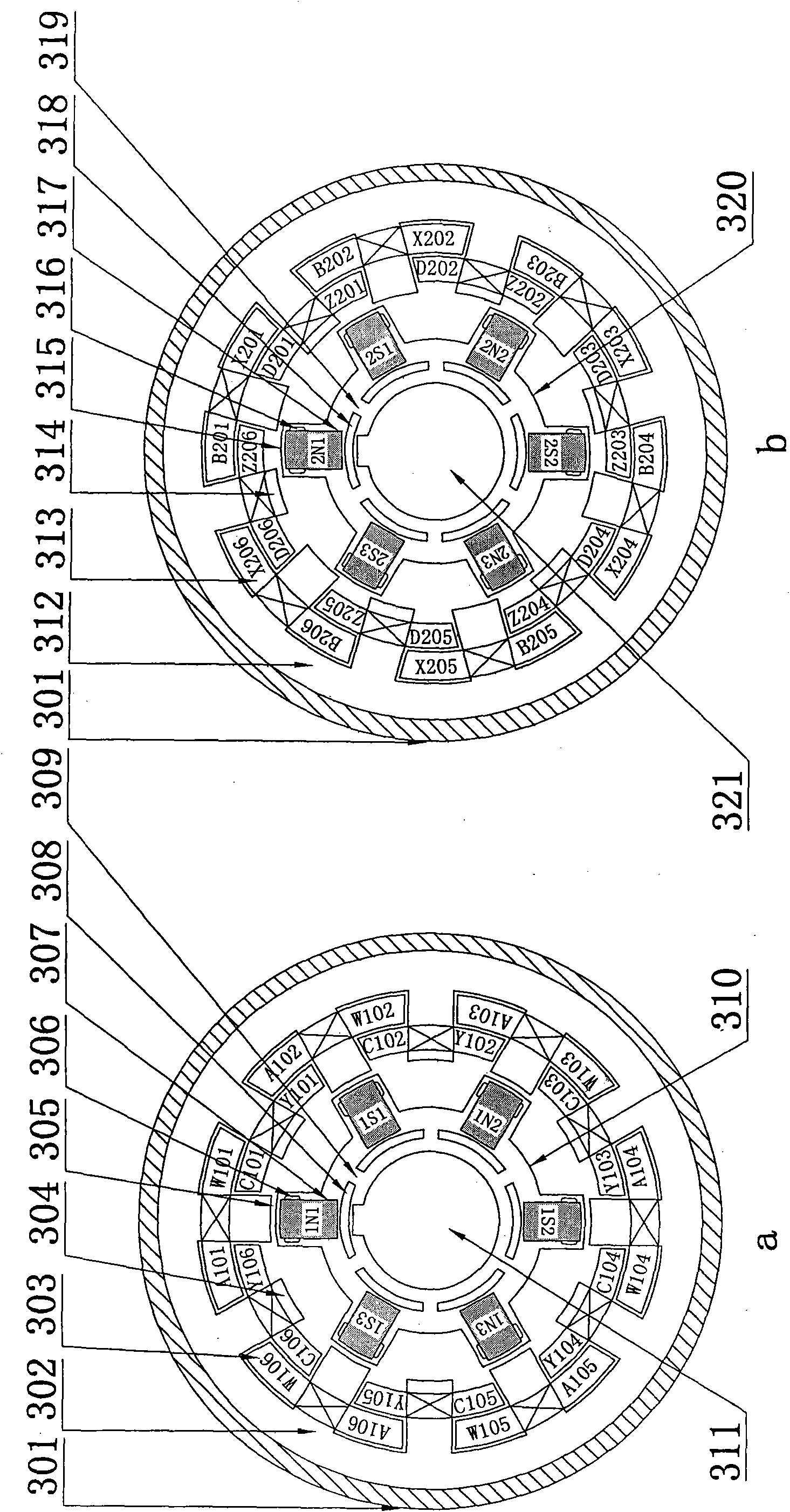
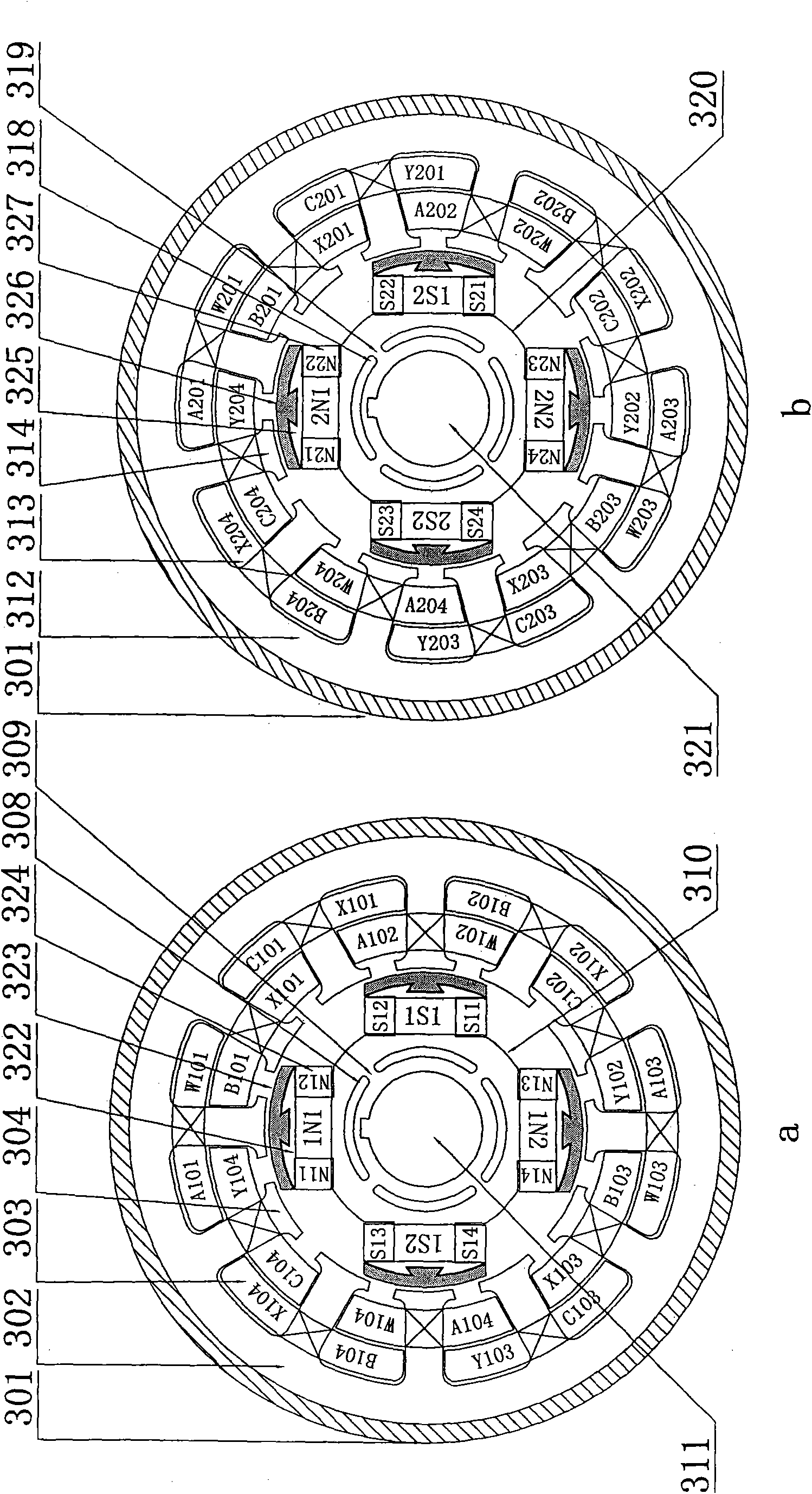
[0044] Below in conjunction with accompanying drawing and embodiment the present invention will be further described

[0045] refer to figure 1 , Figure 5 , a permanent magnet multi-pole switched reluctance motor in the figure, the rotor pole is a built-in radial permanent magnet pole, the motor casing 301 is placed on the motor foot 346 through the motor foot fixing screw hole 345, and the middle part of the motor casing 301 is set There is a motor suspension ring 334, the motor front end cover 332 and the rear end cover 339 are respectively arranged on the two ends of the motor shaft through the front bearing 331 and the rear bearing 340, and the motor front end cover 332 and the rear end cover 339 are fixedly connected with the motor housing 301 through the fixing screw 333 , the outer end of the motor rear end cover 339 is provided with a windshield 344, the windshield 344 is provided with a motor fan 341, and an electronic sensor 342 is arranged between the motor fan 34...


PUM


Abstract

A permanent magnet multiple-pole switch reluctance motor comprises a motor casing, a motor shaft extension end, a motor non-shaft extension end and the like which are formed by a stator and a rotor in which are double convex pole structures formed by laminating silicon steel sheets. A stator iron core comprises a first section stator iron core and a second section stator iron core, and a rotor iron core comprises a first section rotor iron core and a second section rotor iron core; each of the stator and the rotor iron cores is composed of single-section two phases and double-section four phases or single-section three phases and double-section six phases; the double-section stator and the double-section rotor have the equal length and diameter; the first section of stator iron core comprises an armature magnetic yoke of the first section stator, a magnetic pole and a magnetic pole winding, two sets of concentrated or sandwich stator magnetic pole windings are arranged on stator magnetic poles, armature windings on magnetic poles of same phase positions of each set of windings are connected in series or in parallel according to the positive polarity or reverse polarity of the stator magnetic poles to form a phase; and the first section rotor iron core comprises a rotor in-built radial permanent magnet pole, a magnetic pole division hole, a permanent magnet, a magnetic pole isolation groove, a magnetic yoke, a rotor magnetic bridge and a rotor shaft hole with a key slot. The permanent magnet multiple-pole switch reluctance motor has the characteristics of energy-saving, high efficiency, high speed and large speed adjustment range.

Description

technical field [0001] The invention relates to the technical field of switched reluctance motors, in particular to a permanent magnet double-pole switched reluctance motor with built-in permanent magnet poles and permanent magnet surface-mounted electric excitation hybrid poles. Background technique [0002] In the prior art, the switched reluctance motor is a doubly salient pole reluctance motor, and the salient poles of the stator and rotor are laminated by ordinary silicon steel sheets; the rotor has neither winding nor permanent magnet, and concentrated windings are wound on the stator poles , The two radially opposite windings are connected together, which is called "one phase". The motor can be designed into a variety of different phase structures, and the number of poles of the stator and rotor can be matched in many different ways. The number of phases is large and the step angle is small, which is conducive to reducing torque ripple, but the structure is complex, a...

Claims


Application Information

Patent Timeline
Patent Type & Authority Patents(China)
IPC IPC(8): H02K29/03H02K3/28H02K1/27H02K13/00
Inventor 张世清张红梅
Owner 张世清
Why Eureka
Try Eureka