Method for balancing the out-of-balance of a shaft/wheel assembly

Pending Publication Date: 2022-01-06
DATATECHNIC SAS
View PDF10 Cites 0 Cited by
  • Summary
  • Abstract
  • Description
  • Claims
  • Application Information

AI Technical Summary

Benefits of technology

The invention relates to a method for balancing a shaft-wheel assembly with a bladed wheel. The method involves measuring the positions of target areas on the bladed wheel and removing a quantity of material to reduce out-of-balance values. The positions of the target areas can be measured using a tool applied against the surface of the bladed wheel, which is active during the measurement. This allows for more accurate detection of the position of the target areas even when the grinding means is off-centred. The required balancing time is reduced by suppression of a step of activating the grinding means during the method.

Problems solved by technology

That way, a poor balance between the mechanical shaft and the turbine wheel is liable to generate vibrations, which might cause noise pollution as a whistle as well as a premature wear of the turbocharger.
Usually, the turbine wheels are cast parts, whose raw surface does not permit the accurate welding thereof to the end of a mechanical shaft.
Moreover, during the welding, the filling metal distribution on the welded part is not either well controlled.
Now, the raw surface of the turbine wheels does not permit a very accurate control of their inclination angle with respect to the axis of rotation of the mechanical shaft during their welding.
This inaccuracy results in an offsetting of the turbine wheel surface by a few tenths of millimetres with respect to its theoretical position when held by a base.
These repeated balancing operations have for drawback to slow down the production rate of said parts, and to a lesser extent, to weaken the structure thereof.

Method used


Image

  • Method for balancing the out-of-balance of a shaft/wheel assembly
  • Method for balancing the out-of-balance of a shaft/wheel assembly
  • Method for balancing the out-of-balance of a shaft/wheel assembly

Examples


Embodiment Construction

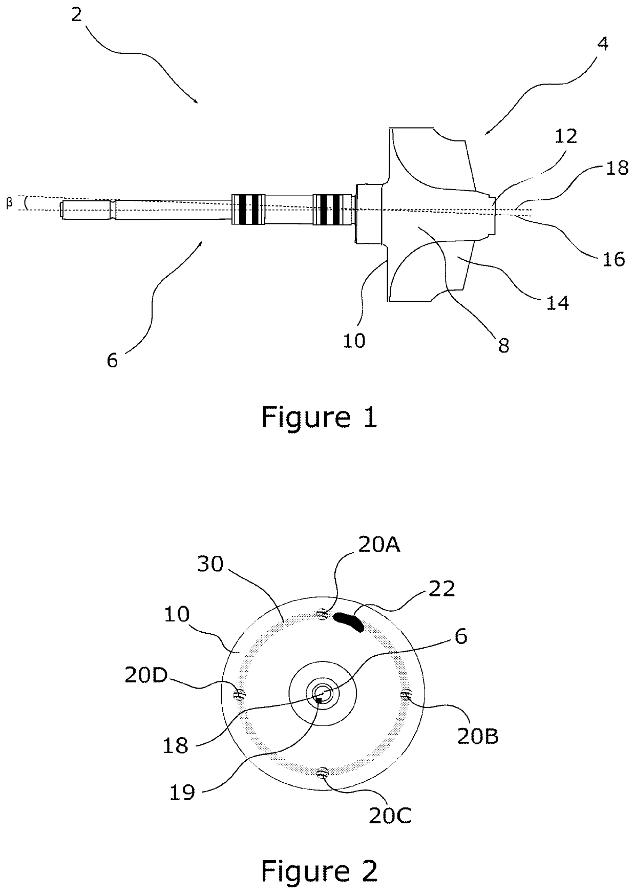
[0039]According to the invention, it is meant by shaft-wheel assembly 2, a bladed wheel 4 held at the end of a mechanical shaft 6, as illustrated in FIG. 1. As known, a bladed wheel comprises a hub 8 of conical or substantially conical shape, extending between a rear face 10 and a nose 12. The bladed wheel includes a plurality of wings 14 extending radially from the hub 8. The wings are distributed at regular intervals about said hub, so as to enable a flow of air to make the bladed wheel 4 pivoting about an axis of rotation 16, passing through the centre of the rear face 10 and the centre of the hub nose 12.

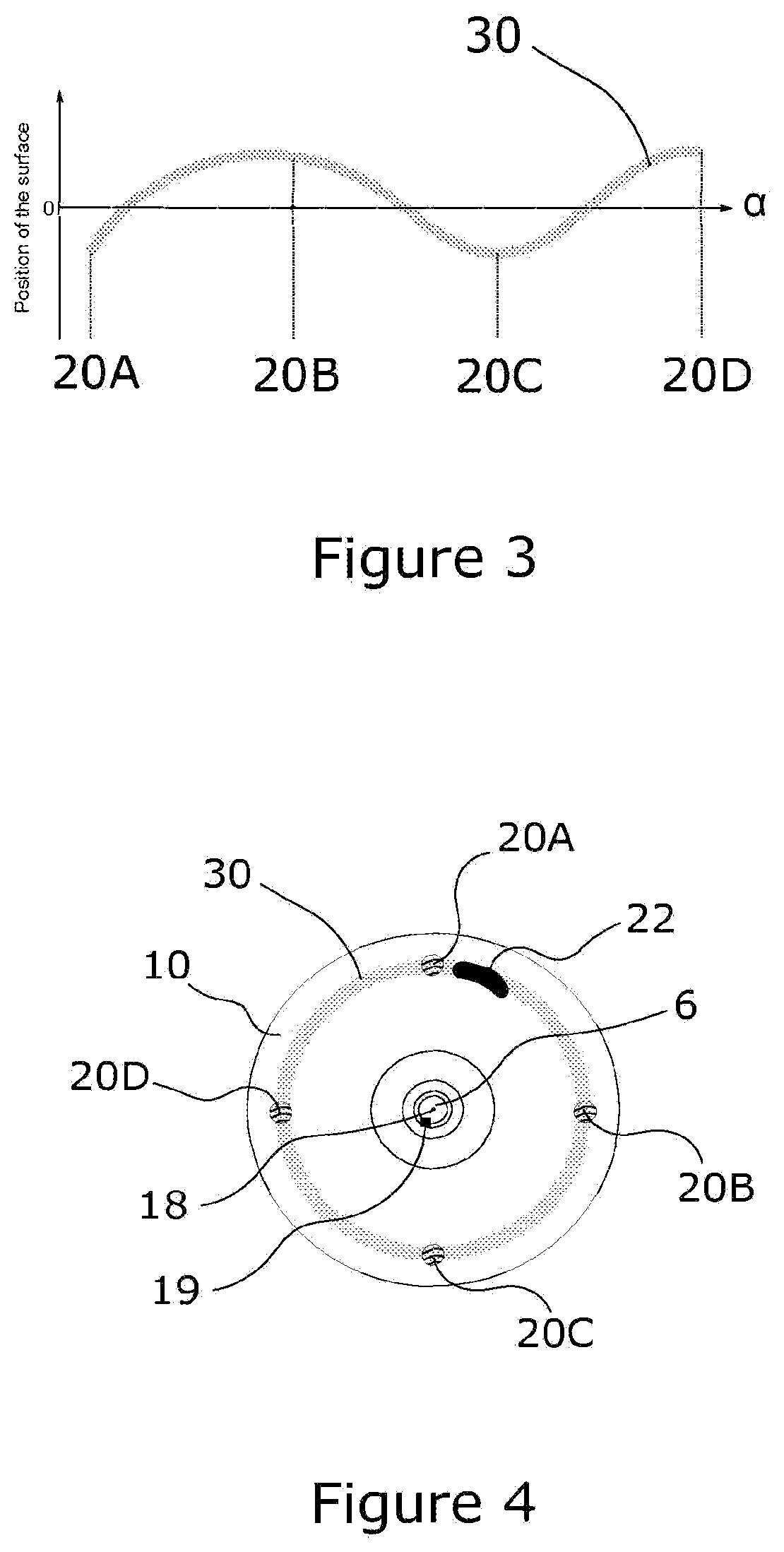
[0040]The bladed wheel 4 is usually a casted part whose raw surface prevents an accurate welding of the latter on one end of the mechanical shaft 6. That way, the axis of rotation 16 of the bladed wheel and the axis of rotation 18 of the mechanical shaft 6 are slightly offset with respect to each other and inclined by an angle β as illustrated in FIG. 1. The centre of inertia 19...


PUM


Abstract

Disclosed is a method for balancing the out-of-balance of a shaft / wheel assembly. The balancing method involves a step of measuring the value of the out-of-balance of a wheel / shaft assembly with respect to a longitudinal axis of the mechanical shaft, and then measuring the position of at least two different target zones present on the surface of the wheel. The method involves removing material from the surface of the vaned wheel in order to reduce the value of the out-of-balance of the shaft / wheel assembly depending on the measurements taken in steps a) and b). In this way, the balancing method is much more precise compared with the prior art.

Description

TECHNICAL FIELD TO WHICH THE INVENTION RELATES[0001]The present invention relates to a method for balancing the out-of-balance of a shaft-wheel assembly, comprising a bladed wheel held at the end of a mechanical shaft. In particular, it relates to a method for balancing the out-of-balance of a turbocharger part for a heat engine, comprising a turbine wheel welded to the end of a mechanical shaft. The present invention also relates to an automated balancing station, adapted to implement the balancing method.TECHNOLOGICAL BACK-GROUND[0002]In a known manner, a turbocharger makes it possible to increase the efficiency of a heat engine. For that purpose, the turbocharger comprises a turbine wheel held at one end of a mechanical shaft and a compressor wheel held at another end of said shaft. The turbine wheel is placed in the exhaust gas flow of the engine, so that the compressor wheel is driven in rotation through the mechanical shaft. The compressor wheel is placed in the intake duct of...

Claims


Application Information

Patent Timeline
IPC IPC(8): F01D5/02G01M1/24G01M1/34
CPCF01D5/027G01M1/24F05D2230/10F05D2220/40G01M1/34G01B21/22
Inventor SILLON, CHRISTOPHE
Owner DATATECHNIC SAS
Why Eureka
Try Eureka