Chain transmission device

Pending Publication Date: 2022-01-06
DAIDO KOGYO CO LTD
View PDF0 Cites 0 Cited by
  • Summary
  • Abstract
  • Description
  • Claims
  • Application Information

AI Technical Summary

Benefits of technology

The present invention is a chain transmission device that reduces frictional resistance between the chain and the chain guide by minimizing the contact area between them. The friction modifier added to the lubricating oil matches the material of the link plate, preventing an increase in frictional resistance even in boundary lubrication. The device includes a chain, outer links with link plates, and inner links with link plates. The link plates have convex portions on their back surface in a round shape that reduce the area in contact with the chain guide. Additionally, the invention uses a friction modifier containing a molybdenum compound, which promotes the formation of molybdenum disulfide coating film and reduces friction. Coating film surface roughness is also controlled to prevent an increase in friction loss during boundary lubrication. Overall, the invention improves the performance of the chain transmission device.

Problems solved by technology

Thus, a friction loss increases and a gap may be defined between a back surface of a guide link plate and a guide surface of the chain guide, which may cause unstable behaviors of the chain.

Method used


Image

  • Chain transmission device
  • Chain transmission device
  • Chain transmission device

Examples


Embodiment Construction

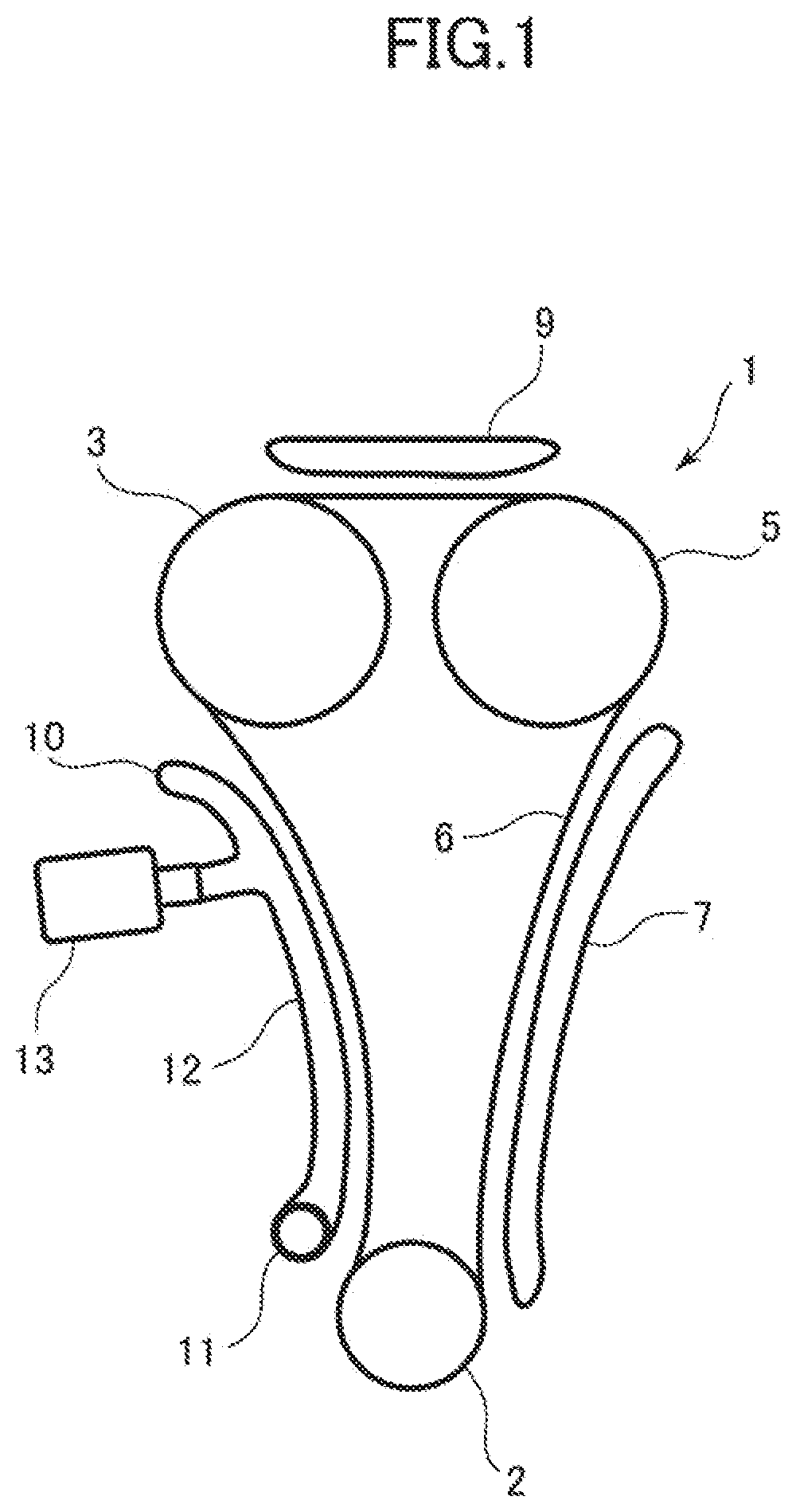
[0055]Hereinafter, embodiments of the invention will be described with reference to the drawings. FIG. 1 shows a timing chain transmission device 1 to which the invention can be applied. The timing chain transmission device 1 is disposed in an engine and used under a lubricating environment. The timing chain transmission device 1 includes a drive side sprocket 2 fixed to a crankshaft, driven side sprockets 3, 5 respectively fixed to two camshafts, and a chain 6 wound among the drive side sprocket 2 and the driven side sprockets 3, 5. Chain guides 7, 9, 10 are in sliding contact with a back surface side of the chain 6 to guide the chain. The chain guide 7 on a tension side between the drive side sprocket 2 and the driven side sprocket 5 and the chain guide 9 between the two driven side sprockets 3, 5 are formed of rail-shaped shoe members attached to fixing members. The chain guide 10 between the drive side sprocket 2 and the driven side sprocket 3 is formed of a chain tensioner. The...


PUM


Abstract

When a contact area with a chain guide is reduced to a small area by forming a back surface of a link plate into a convex portion having a round shape or the like, a friction coefficient in a fluid lubrication region is reduced (region E). A coating film containing 10% or more of chromium is formed on the link plate. A friction modifier made of a molybdenum compound such as MoDTC and added to a lubricating oil promotes generation of MoS2 by the chromium coating film, and prevents an increase in the friction coefficient in a boundary lubrication region.

Description

CROSS-REFERENCE TO RELATED APPLICATIONS[0001]This application is a Continuation of International Patent Application No. PCT / JP2019 / 012275, filed Mar. 22, 2019, which is hereby incorporated by reference herein in its entirety.BACKGROUND OF THE INVENTIONField of the Invention[0002]The present invention relates to a chain transmission device in which a back surface of a chain is guided by a chain guide under a lubricating environment, and more particularly, to a chain transmission device suitable for application to a chain transmission device in an engine.Background Art[0003]In general, in a timing chain transmission device that transmits rotation of a crankshaft of an engine to a camshaft, a back surface of a chain is guided by a chain guide. When a silent chain is used as the chain, a back surface of an inner (toothed) link plate of the silent chain is a linear flat surface, and the entire back surface is in sliding contact with the chain guide. Thus, a friction loss increases and a ...

Claims


Application Information

Patent Timeline
IPC IPC(8): F16G13/04F16H7/06F16H57/05
CPCF16G13/04F16H57/05F16H7/06F16G13/08F16G13/07
Inventor TANAKA, MOTOKIYAMASHITA, SATOSHINAKAGAWA, HIROKIHAYASHI, ATSUSHI
Owner DAIDO KOGYO CO LTD
Why Eureka
Try Eureka