Ballistic unipolar bistable actuator

Pending Publication Date: 2022-01-06
MOVING MAGNET TECH
View PDF0 Cites 0 Cited by
  • Summary
  • Abstract
  • Description
  • Claims
  • Application Information

AI Technical Summary

Benefits of technology

[0013]One of the objects of the present disclosure is thus to provide an actuator that still meets the need to achieve bidirectional movement while keeping two stable end-of-stroke positions and

Problems solved by technology

This results in a loss of energy and in heating of the actuator.
However, this bipolarity of the current requires an electronic architecture that is more complex and expensive than in the unipolar case because it is generally necessary to integrate several switching transistors (according to an assembly typically referred to as an “H-bridge”), and the availability of such architectures may prove problematic in an automotive electrical network, especially when it is necessary to multiply the functions and therefore the availability of this architecture.
However, all of these solutions have defects inherent to the very principles of the mechanical systems used to generate these stable positions or to systems requiring a powe

Method used


Image

  • Ballistic unipolar bistable actuator
  • Ballistic unipolar bistable actuator
  • Ballistic unipolar bistable actuator

Examples


Embodiment Construction

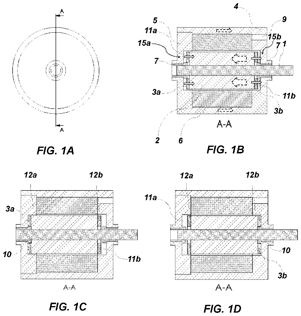
[0034]An example of a device according to the present disclosure is shown in FIGS. 1A to 1D, the views 1b to 1d being sectional views along the plane shown in FIG. 1A. In this embodiment, the device is a linear actuator of axisymmetric shape, but without the shape being limiting, a rectangular parallelepiped shape also being possible, for example, as well as a rotary configuration such as that shown in FIG. 6.

[0035]The device described here comprises an axis (1) moving linearly and axially relative to the axisymmetric shape. In the view of FIG. 1B, the axis is secured to a mobile mass (2) on which permanent magnets (3a, 3b) are positioned axially on either side of the mobile mass (2). The assembly of the axis (1), mobile mass (2) and permanent magnets (3a, 3b) constitutes an apparatus that is mobile in translation and axially from a first position to a second position or vice versa. The two end positions adopted by this mobile apparatus are shown in FIGS. 1C and 1D. These two positi...


PUM


Abstract

An actuator for controlling the movement of an element between two stable positions with pulsed electrical control without a change in polarity comprises: a ferromagnetic mobile mass, at least one electrically controlled wire coil that is fixed with respect to the mobile mass, at least two ferromagnetic poles that are fixed with respect to the mobile mass and on either side of the mobile mass. The actuator comprises at least one permanent magnet that attracts the mobile mass in order to achieve the two stable positions. The mobile mass defines, with the ferromagnetic poles, at least two variable air gaps during the movement of the mobile apparatus. The magnetic flux of the permanent magnet opposes the magnetic flux generated by the at least one coil regardless of the position of the mobile mass.

Description

CROSS-REFERENCE TO RELATED APPLICATIONS[0001]This application is a national phase entry under 35 U.S.C. § 371 of International Patent Application PCT / FR2019 / 052441, filed Oct. 16, 2019, designating the United States of America and published as International Patent Publication WO 2020 / 084220 A1 on Apr. 30, 2020, which claims the benefit under Article 8 of the Patent Cooperation Treaty to French Patent Application Serial No. 1859948, filed Oct. 26, 2018.TECHNICAL FIELD[0002]The present disclosure relates to the field of actuators having two stable positions in the absence of current.[0003]Electromagnetic actuators are generally made in a monostable manner, which is to say, that the magnetic armature of the actuator—when it is not supplied with energy—has a single stable position without current. This stable position is generally determined by the return force of a spring, while the transfer to the other end position on the stroke, called the switched position, is achieved by energizin...

Claims


Application Information

Patent Timeline
IPC IPC(8): H01F7/122H01F1/14H01F7/14H01F7/16H01F7/18
CPCH01F7/122H01F1/14H01F7/14H01F2007/1692H01F7/1872H01F2007/1669H01F7/1615H01F7/18H01F7/1844
Inventor LOUSSERT, GUILLAUMEBIWERSI, STÉPHANE
Owner MOVING MAGNET TECH
Why Eureka
Try Eureka