Seal assembly

Active Publication Date: 2022-01-13
CUMMINS LTD WEST YORKSHIRE
View PDF0 Cites 2 Cited by
  • Summary
  • Abstract
  • Description
  • Claims
  • Application Information

AI Technical Summary

Benefits of technology

[0031]Advantageously, this provides the sealing portion with increased resilience and can therefore allow a desired predetermined speed at which the sealing pressure provided by the sealing portion is zero to be achieved.
[0032]According to a second aspect of the disclosure there is provided a rotary seal for use in a seal assembly of a turbomachine, the rotary seal comprising a base; a sealing portion; and an intermediate portion located between the base and the sealing po

Problems solved by technology

Seals are typically made of elastomeric or rubber materials which are not suitable for prolonged high temperature operation.
If suc

Method used


Image

  • Seal assembly
  • Seal assembly
  • Seal assembly

Examples


Embodiment Construction

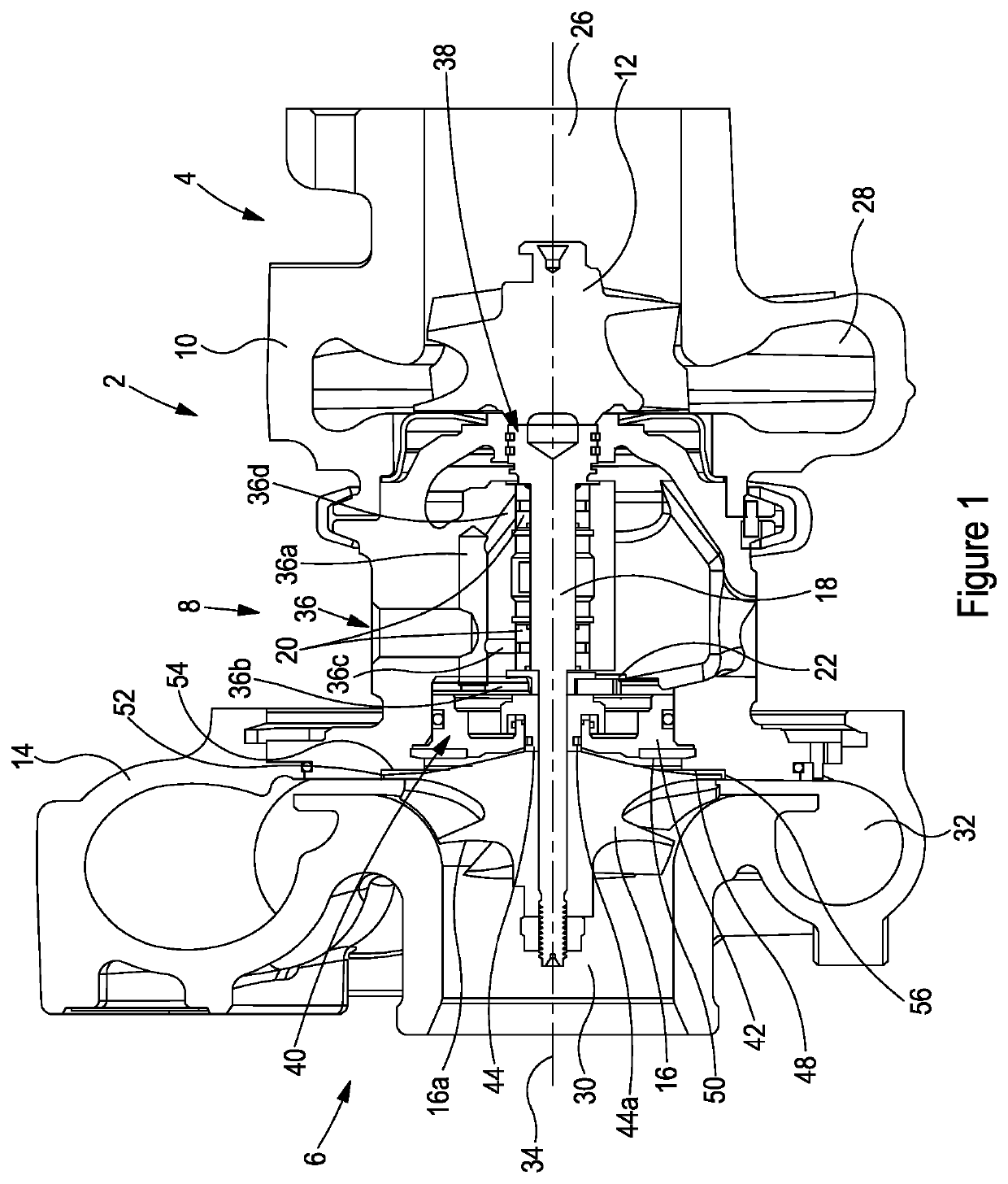
[0063]FIG. 1 is a cross-sectional side view of a turbocharger 2 according to a first aspect of the disclosure. The turbocharger comprises a turbine 4 joined to a compressor 6 via a bearing housing 8. The turbine 4 comprises a turbine housing 10 and a turbine impeller 12. Similarly, the compressor 6 comprises a compressor housing 14 and a compressor impeller 16. The turbine impeller 12 and compressor impeller 16 are mounted on opposite ends of a shaft 18 which is supported on radial bearing assemblies 20 and a thrust bearing assembly 22 within the bearing housing 8. 20 may comprise plain bearings. Alternatively, the radial bearing assemblies 20 may comprise roller bearings. The radial bearing assemblies 20 may be any bearing which can support a predominantly radial load,> The radial bearing assemblies 20 support a predominantly rotational load whilst the thrust bearing assembly 22 supports a predominantly axial load. Although a fixed geometry turbocharger is shown in FIG. 1, the disc...


PUM


Abstract

A seal assembly for use in a turbomachine, the seal assembly comprising an oil seal plate; a rotatable component which defines a central axis and is received in a central aperture of the oil seal plate; and an annular seal which comprises a base and a sealing portion, the base being held by the rotatable component; wherein the sealing portion is configured to form a seal with the oil seal plate when the rotatable component and annular seal are rotating below a predetermined rotational speed; and wherein the sealing portion is configured to move radially outwards with respect to the central axis such that the sealing portion loses contact with the oil seal plate when the rotatable component and annular seal are rotating above the predetermined rotational speed.

Description

CROSS-REFERENCE TO RELATED APPLICATIONS[0001]The present application is a national stage application of International (PCT) Patent Application Serial No. PCT / GB2019 / 053510, filed on Dec. 11, 2019, which claims the benefit of United Kingdom Application No. 1820435.4, filed Dec. 14, 2018, the complete disclosures of which are expressly incorporated by reference herein.FIELD OF DISCLOSURE[0002]The present disclosure relates to a seal assembly for use in a turbomachine.BACKGROUND[0003]Turbochargers are well known devices for supplying air to the intake of an internal combustion engine at pressures above atmospheric pressure (boost pressures). A conventional turbocharger comprises an exhaust gas driven turbine wheel mounted on a rotatable shaft within a turbine housing. Rotation of the turbine wheel rotates a compressor wheel mounted on the other end of the shaft within a compressor housing. The compressor wheel delivers compressed air to the intake manifold of the engine, thereby increa...

Claims


Application Information

Patent Timeline
IPC IPC(8): F04D29/16F04D19/00F16J15/00
CPCF04D29/164F16J15/002F04D19/002F01D25/18F01D25/183F01D5/04F01D11/003F01D11/00F01D25/16F05D2240/55F05D2240/50Y02T10/12
Inventor PURDEY, MATTHEW J.
Owner CUMMINS LTD WEST YORKSHIRE
Why Eureka
Try Eureka