Agricultural sprayer with warm water rinse system

Pending Publication Date: 2022-01-20
AGCO INT GMBH
View PDF1 Cites 0 Cited by
  • Summary
  • Abstract
  • Description
  • Claims
  • Application Information

AI Technical Summary

Benefits of technology

The patent describes a system and method for using heated water to effectively clean and remove chemical residues from a sprayer. Using heated water makes it easier to remove difficult or sticky residues. This system also reduces the amount of water required for cleaning, which can make it more cost-effective. Additionally, using heated water can help to cool the system, reducing the size and energy input needed for the cooling system. Overall, this system provides improved cleaning efficiency and reduces the amount of water needed.

Problems solved by technology

However, such excessive use of water can be relatively wasteful, as well as resulting in increased cost levels for sprayer operators.
In addition, sprayers can often be required to return to a centralized depot for a cleaning operation, if the relatively large volumes of rinse water or cleaning solutions are too bulky to transport with the sprayer itself.

Method used


Image

  • Agricultural sprayer with warm water rinse system
  • Agricultural sprayer with warm water rinse system
  • Agricultural sprayer with warm water rinse system

Examples


second embodiment

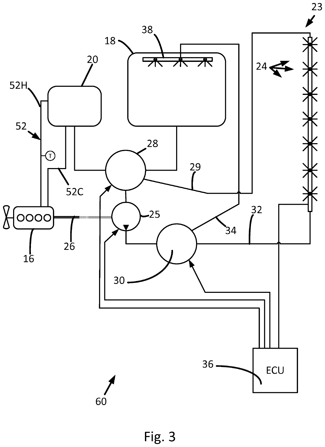
[0047]With reference to FIG. 3 a spray system 60 uses a different heat exchange system to that shown in FIG. 2 and described above in relation to heating the rinse fluid. In this embodiment, waste heat from the engine 16 is recovered and transferred directly to the rinse fluid.

[0048]The heat exchange system 52 uses the rinse fluid itself as a heat exchange medium by transporting the rinse fluid from the rinse tank 20 to a heat exchanger associated with engine 16 and returning the heated fluid to the rinse tank 20. The fluid circuit comprises a heated line 52H and a cooled line 52C. The fluid may be circulated by a water pump (not shown) drivingly connected to the engine 16.

third embodiment

[0049]With reference to FIG. 4, a spray system 70 uses waste heat from parts of an on-board hydraulic system, in this case the pump 25. It should be understood that engine 16 and the input manifold control line have been omitted from FIG. 4 only for reasons of clarity. In this embodiment, waste heat from the pump 25 is recovered and transferred directly to the rinse fluid.

[0050]A heat exchange system 62 comprises a heat exchanger 64 that is mounted proximate to, or integrated with, the pump 25. The heat exchanger 64 is connected in a fluid circuit having a heated line 62H and a cooled line 62C. The cooled line 62C conveys rinse fluid from rinse tank 20 to the heat exchanger 64, whereas the heated line conveys heated rinse fluid from the heat exchanger 64 to the rinse tank 20. A pump (not shown) may be provided in the fluid circuit to force movement of the rinse fluid.

[0051]In the embodiment illustrated by FIG. 4 the rinse fluid is heated directly by the heat exchange system 62. Howe...


PUM


Abstract

An agricultural crop sprayer includes a product tank for holding a solution of plant protection product, a product dispense system, and a rinse tank for holding a rinse fluid. A plumbing network fluidly connects the product tank, the product dispense system, and the rinse tank. A heat source is provided to heat the rinse fluid. The heat source may be a prime mover or a hydraulic pump, wherein waste heat is scavenged therefrom.

Description

CROSS-REFERENCE TO RELATED APPLICATIONS[0001]This application is a national phase entry under 35 U.S.C. § 371 of International Patent Application PCT / EP2019 / 082874, filed Nov. 28, 2019, designating the United States of America and published in English as International Patent Publication WO 2020 / 126386 A1 on Jun. 25, 2020, which claims the benefit of the filing date of United Kingdom Patent Application GB1820704.3, “Agricultural Sprayer with Warm Water Rinse System,” filed Dec. 19, 2018, the entire disclosure of which is incorporated herein by reference.FIELD[0002]The present invention relates to an agricultural sprayer and a method of operating such a sprayer.BACKGROUND[0003]Agricultural sprayers are used in the application of various materials to field crops. Such systems apply various chemicals in the form of a spray for the purposes of crop protection, e.g., through the use of appropriate pesticides or herbicides, or for the purposes of limiting or promoting plant growth, e.g., t...

Claims


Application Information

Patent Timeline
IPC IPC(8): B08B9/093A01M7/00A01C15/00
CPCB08B9/093A01M7/0089A01M7/0085B08B2203/007A01C15/005B08B2209/08A01M7/005A01M7/00
Inventor SCHELL, DAAN
Owner AGCO INT GMBH
Why Eureka
Try Eureka