
Radiating element of antenna and antenna

Pending Publication Date: 2022-01-20
SAMSUNG ELECTRONICS CO LTD
View PDF0 Cites 0 Cited by
  • Summary
  • Abstract
  • Description
  • Claims
  • Application Information

AI Technical Summary

Benefits of technology

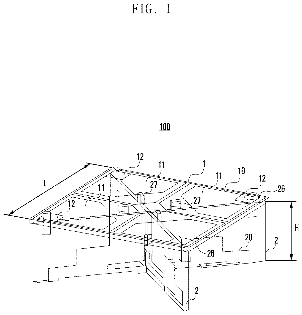
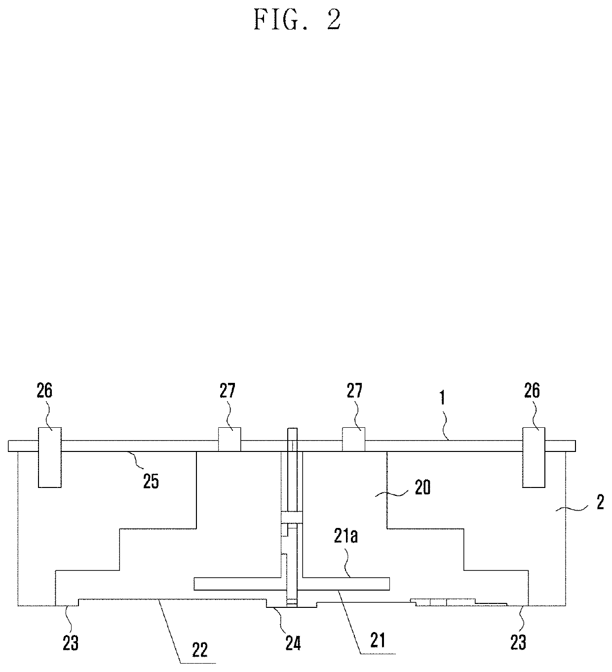
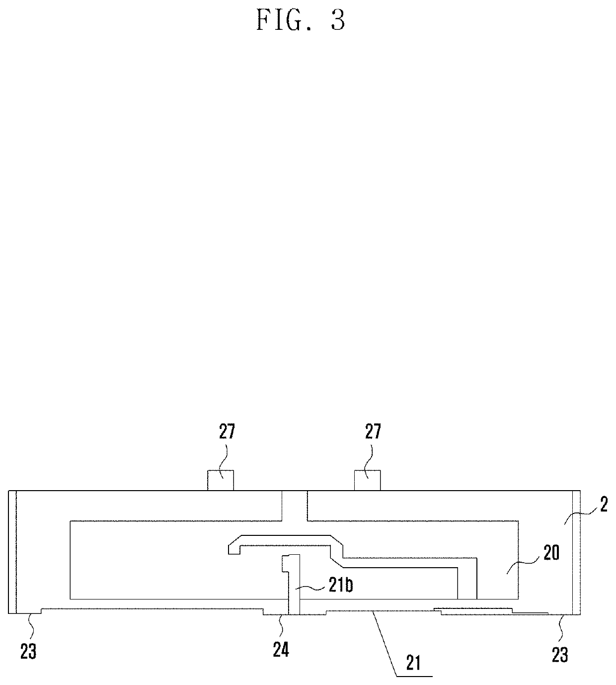
This patent describes a new design for an antenna that reduces the size and volume of the radiating element, while also improving performance and bandwidth. The design includes a radiating element made up of two printed circuit boards, which simplifies assembly and welding, and allows for a more efficient manufacturing process. Additionally, the design includes a metallized pillar and inner convex metallized sheet which help to compensate for any deterioration in performance due to the smaller size of the antenna. Overall, this design results in a smaller, more efficient, and better performing antenna.

Problems solved by technology

The hot shrinkage deformation and weight of the die-cast vibrator has always been a serious constraint problem.
In addition, the die-cast vibrator requires mold manufacturing, and is manufactured with low precision and poor consistency.
In order to widen the bandwidth, it is often necessary to add a metal pillar at an end corner of the vibrator, which not only increases the manufacturing process and cost, but also has low precision and poor consistency.
It is necessary to increase isolation, which leads to an increase in the overall weight and volume of the antenna.
Although the weight of the combination sheet metal vibrator is lighter, an assembly process is complicated and it is not easy to implement surface mount technology (SMT) assembly.
It can be seen that the existing various antenna vibrators cannot address the issues of large size, medium weight, narrow bandwidth and poor isolation at the same time, so that they cannot adapt to requirements of 5G-MIMO (the fifth generation mobile communication technology—multiple input and multiple output antenna).
However, compared with the prior art, the cost and process may not be increased.

Method used


Image

  • Radiating element of antenna and antenna
  • Radiating element of antenna and antenna
  • Radiating element of antenna and antenna

Examples


Embodiment Construction

[0044]The following description with reference to the accompanying drawings is provided to assist in a comprehensive understanding of various embodiments of the disclosure as defined by the claims and their equivalents. It includes various specific details to assist in that understanding but these are to be regarded as merely exemplary. Accordingly, those of ordinary skill in the art will recognize that various changes and modifications of the various embodiments described herein can be made without departing from the scope and spirit of the disclosure. In addition, descriptions of well-known functions and constructions may be omitted for clarity and conciseness.

[0045]The terms and words used in the following description and claims are not limited to the bibliographical meanings, but, are merely used by the inventor to enable a clear and consistent understanding of the disclosure. Accordingly, it should be apparent to those skilled in the art that the following description of variou...


PUM


Abstract

The disclosure relates to a pre-5th-Generation (5G) or 5G communication system to be provided for supporting higher data rates Beyond 4th-generation (4G) communication system, such as long term evolution (LTE). A radiating element of an antenna is provided. The radiating element includes a vibrator radiating circuit board, wherein vibrator radiating arms arranged in pairs are printed on the vibrator radiating circuit board, a width of the vibrator radiating arms is less than one-half of a wavelength, a vibrator balun circuit board, configured to support the vibrator radiating circuit board, wherein a vibrator balun is printed on the vibrator balun circuit board, a height of the vibrator balun is at least less than one-fifth of the wavelength, the vibrator balun comprises at least one first slot. Based on the disclosure, especially for a large array base station and micro base station of 5G-massive multiple-input multiple-output (MIMO), the overall performance of the antenna, such as bandwidth, isolation, gain, cross polarization, or the like, may be improved, and the volume of the antenna is reduced with relatively small performance loss.

Description

CROSS-REFERENCE TO RELATED APPLICATION(S)[0001]This application is a continuation application, claiming priority under § 365(c), of an International application No. PCT / KR2020 / 004411, filed on Mar. 31, 2020, which is based on and claims the benefit of a Chinese patent application No. 201910256652.4, filed on Apr. 1, 2019, in the Chinese Intellectual Property Office, the disclosure of which is incorporated by reference herein in its entirety.BACKGROUND1. Field[0002]The disclosure relates to antenna technology. More particularly, the disclosure relates to a radiating element of an antenna and an antenna to which the radiating element is applied.2. Description of Related Art[0003]To meet the demand for wireless data traffic having increased since deployment of 4th generation (4G) communication systems, efforts have been made to develop an improved 5th generation (5G) or pre-5G communication system. Therefore, the 5G or pre-5G communication system is also called a ‘Beyond 4G Network’ or...

Claims


Application Information

Patent Timeline
IPC IPC(8): H01Q1/38H01Q19/10
CPCH01Q1/38H01Q1/48H01Q19/10H01Q1/36H01Q1/50H01Q21/26H01Q1/246
Inventor WU, AIGUOFUWEN, HONGCHEN, ZHUO
Owner SAMSUNG ELECTRONICS CO LTD
Learn More