
Ceramic heater with shaft

a ceramic heater and shaft technology, applied in the field of ceramic heaters with shafts, can solve the problems of limited ceramic shaft diameter increase increase etc., to achieve the effect of increasing the number of power supply rods, reducing the thickness of the insulating thin film, and increasing the density of the placement of the power supply rods

Pending Publication Date: 2022-01-27
NGK INSULATORS LTD
View PDF0 Cites 0 Cited by
  • Summary
  • Abstract
  • Description
  • Claims
  • Application Information

AI Technical Summary

Benefits of technology

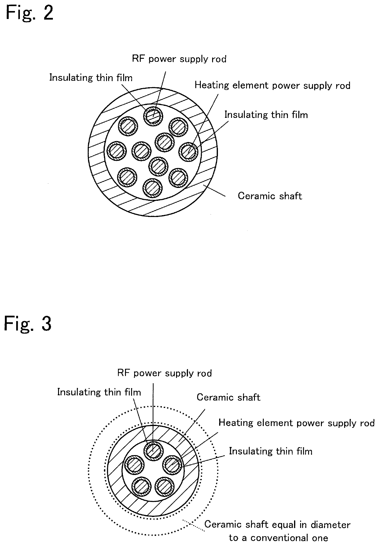
The invention aims to increase the placement density of power supply rods in a ceramic heater with a shaft while ensuring insulation between them. This is achieved by covering the outer circumferential surface of a portion of the power supply rods with an insulating thin film, which is only thick enough to prevent leakage of electricity. This results in a larger number of power supply rods being housed in the inner space of the ceramic shaft, and allows for a smaller diameter of the shaft. The insulating thin film should be between 10 μm and 200 μm in thickness to reliably achieve the desired effect.

Problems solved by technology

However, when the diameter of the ceramic shaft is increased, the temperature uniformity of the wafer placement surface and a wafer is degraded or the stress at the bonding interface between the ceramic shaft and a ceramic plate is increased, thus increase in the diameter of the ceramic shaft is limited.

Method used


Image

  • Ceramic heater with shaft
  • Ceramic heater with shaft
  • Ceramic heater with shaft

Examples


Embodiment Construction

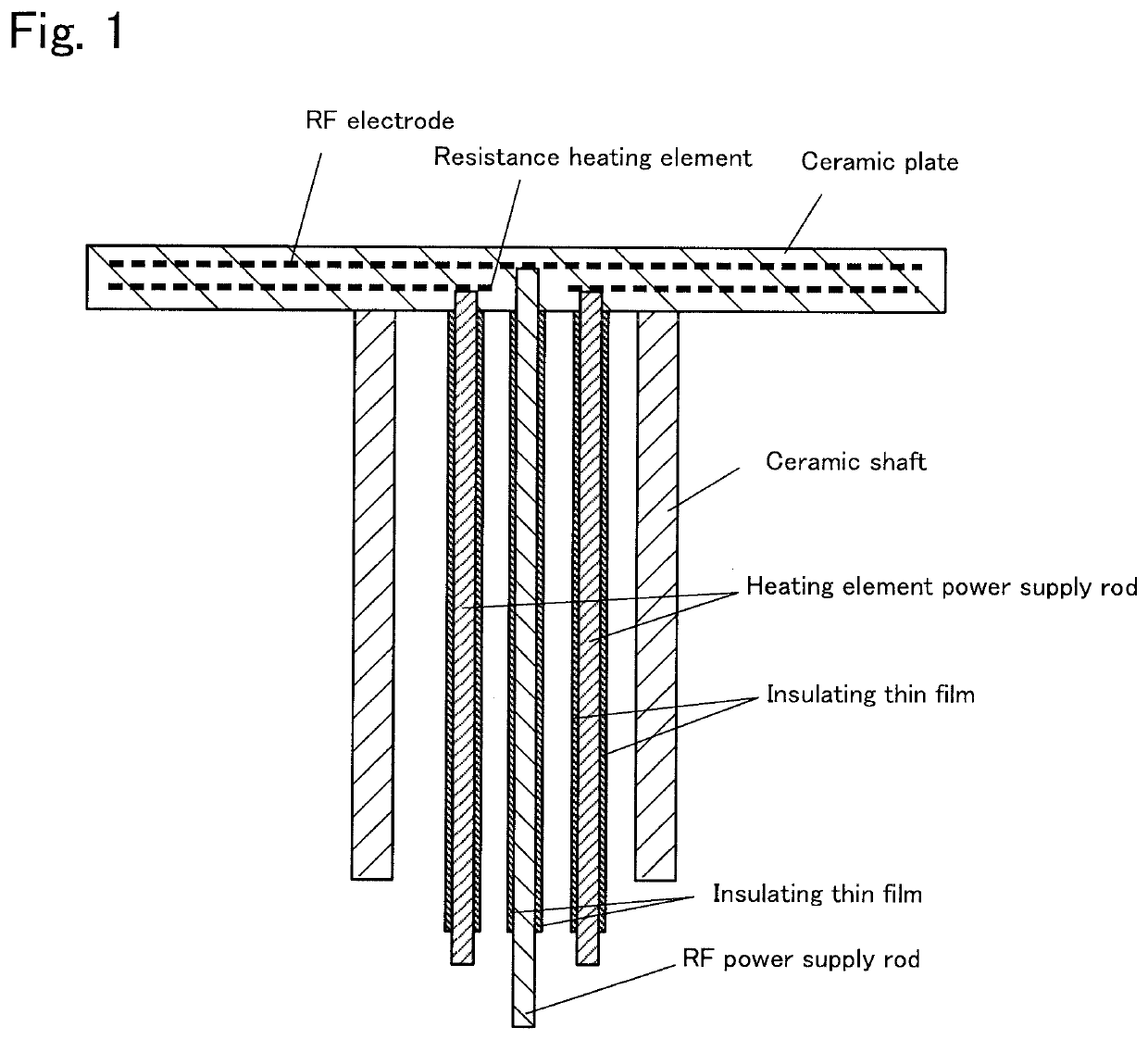
[0019]A preferred embodiment of the present invention will be described hereinafter with reference to the drawings. FIG. 1 is a vertical cross-sectional view of a ceramic heater with a shaft of the present embodiment.

[0020]As illustrated in FIG. 1, the ceramic heater with a shaft includes a ceramic plate, a ceramic shaft, an RF power supply rod, and heating element power supply rods. An RF electrode and resistance heating elements are embedded in the ceramic plate. The RF electrode is an electrode to which a high-frequency voltage is applied when plasma is generated. The resistance heating elements are respectively provided in multiple zones of the ceramic plate. The ceramic shaft is a hollow shaft which is bonded to the surface on the opposite side of the wafer placement surface of the ceramic plate by direct bonding. The RF power supply rod is housed in the inner space of the ceramic shaft, and bonded to the RF electrode from the surface on the opposite side of the wafer placement...


PUM

PropertyMeasurementUnit
thicknessaaaaaaaaaa
thicknessaaaaaaaaaa
resistanceaaaaaaaaaa

Abstract

A ceramic heater with a shaft includes a ceramic plate in which an RF electrode and a resistance heating element are embedded; a hollow ceramic shaft provided on a surface on an opposite side of a wafer placement surface of the ceramic plate; an RF power supply rod which is housed in an inner space of the ceramic shaft, and a heating element power supply rod which is housed in the inner space of the ceramic shaft, wherein an outer circumferential surface of a portion of at least one of the RF power supply rod and the heating element power supply rod is covered with an insulating thin film which is an aerosol deposition film or a thermal spray film, the portion being located in the inner space of the ceramic shaft.

Description

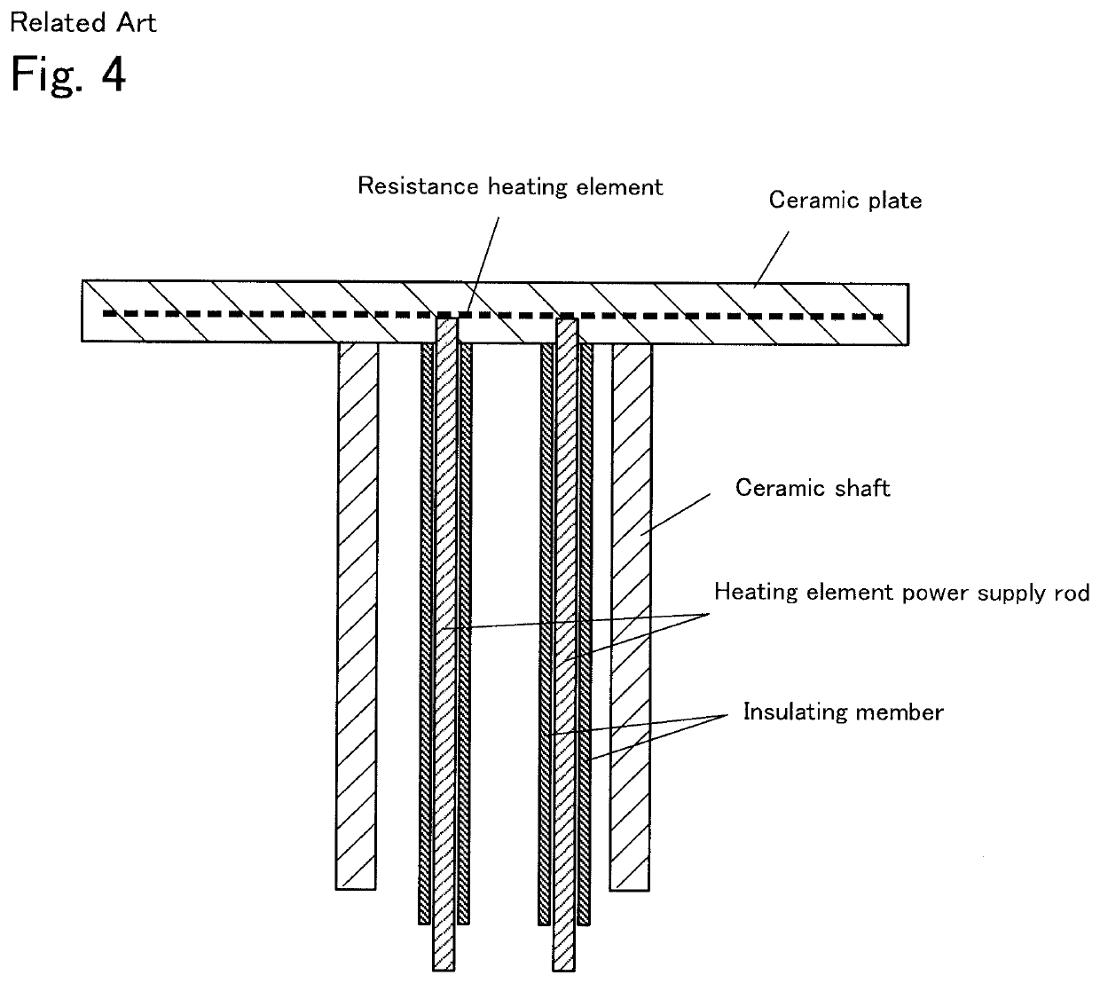
BACKGROUND OF THE INVENTION1. Field of the Invention[0001]The present invention relates to a ceramic heater with shaft.2. Description of the Related Art[0002]In transfer, exposure, a film deposition process such as CVD, washing, etching, and micromachining such as dicing, for a semiconductor wafer, an electrostatic chuck for holding the wafer has been used so far. As shown in PTL 1, such a ceramic heater with a shaft is disclosed, which includes: a ceramic plate in which a resistance heating element is embedded; a hollow ceramic shaft provided on the surface on the opposite side of a wafer placement surface of the ceramic plate; and a heating element power supply rod housed in the inner space of the ceramic shaft (see FIG. 4). The heating element power supply rod is bonded to the resistance heating element from the surface on the opposite side of the wafer placement surface of the ceramic plate. The outer circumferential surface of a portion of the heating element power supply rod i...

Claims


Application Information

Patent Timeline
Patent Type & Authority Applications(United States)
IPC IPC(8): H05B3/14H01L21/67H05B3/03
CPCH05B3/143H05B3/03H01L21/67103H05B3/06H01L21/3065H01L21/683H01L21/02H01L21/6831H01L21/6833H01L21/68792H01L21/68757H05B3/283H05B3/74H05B2203/016H05B2203/017H05B3/141
Inventor AIKAWA, KENICHIROTAKEBAYASHI, HIROSHIKUNO, TATSUYA
Owner NGK INSULATORS LTD
Learn More