

Lifting column and drive system for a lifting system of a furniture
a technology of drive system and lifting column, which is applied in the direction of lifting devices, dynamo-electric components, dynamo-electric machines, etc., can solve the problems unable to lift a tabletop with a specific load at the desired velocity, and having to be dimensioned in the appropriate manner. , to achieve the effect of reducing the space requirement and better protecting from mechanical damag
- Summary
- Abstract
- Description
- Claims
- Application Information
AI Technical Summary
Benefits of technology
Problems solved by technology
Method used
Image

Examples
first embodiment
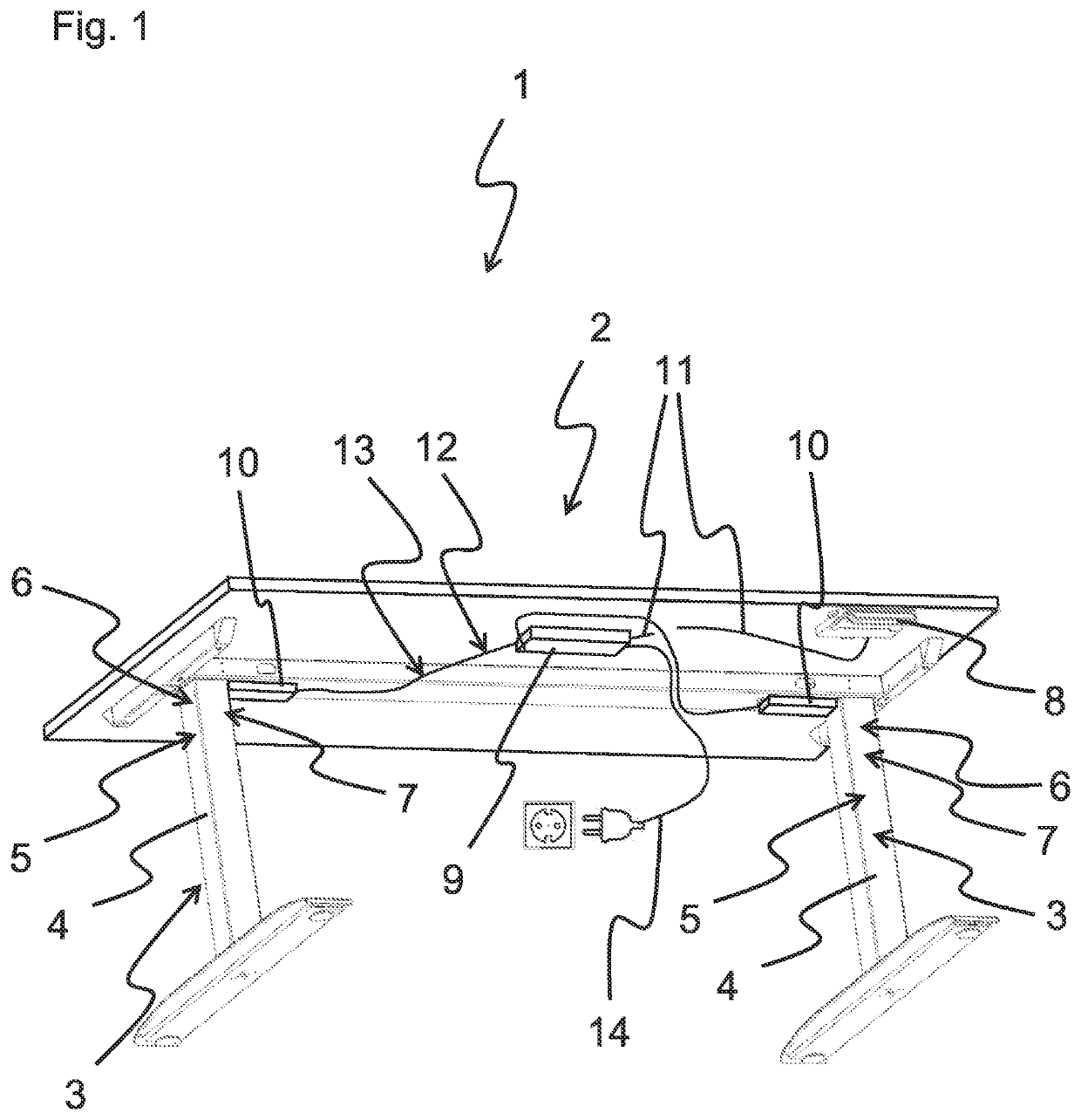
[0042]FIG. 1 shows a table as a furniture 1 having a drive system 2 with lifting columns 3.
[0043]The drive system 2 comprises two lifting columns 3. In alternative embodiments, the drive system 1 merely comprises one lifting column 3 or more than two lifting columns 3.
[0044]The lifting columns 3 respectively comprise two tube portions 4, 5 displaceable with respect to one another like a telescope. Further, the lifting columns 3 respectively comprise a high-voltage direct-current motor 6. Moreover, the lifting columns 3 respectively comprise a transmission 7 for transforming a rotational motion of the high-voltage direct-current motor 6 into a linear motion. The transmission 7 is designed as a spindle-nut system, however, it can alternatively also be designed as, e.g., a tooth belt drive. By the linear motion, the two tube portions displaceable with respect to one another like a telescope are displaced with respect to one another so that a length of the lifting columns 3 is varied in...
second embodiment
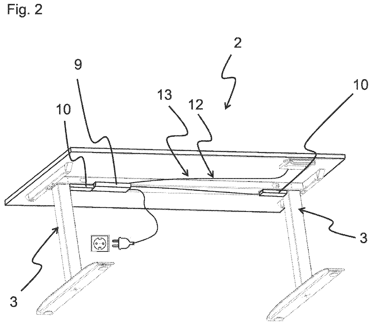
[0058]FIG. 2 shows a table having the drive system 2 having the lifting columns 3.
[0059]The second embodiment of the drive system 2 distinguishes from the first embodiments of the drive system 2 in that the power electronics circuit device 9 is not arranged separately from the control electronics circuit devices 10 but that the power electronics circuit device 9 is attached to one of the lifting columns 3. The power electronics circuit device 9 comprises a housing “docked to” one of the two lifting columns 3, particularly to a housing of the control electronics circuit device 10. Thereby, a connection cable between the power electronics circuit device 9 and the one of the lifting columns 3 can be saved.
[0060]In an alternative embodiment, the power electronics circuit device 9 can be, at least partially, arranged inside the lifting column 3.
[0061]The power electronics circuit device 9 is connected to the other one of the control electronics circuit devices 10 by means of the supply l...
third embodiment
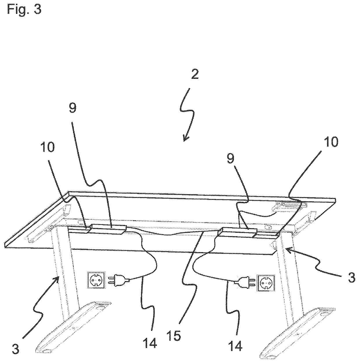
[0062]FIG. 3 shows a table having the drive system 2 having the lifting columns 3.
[0063]The third embodiment of the drive system 2 distinguishes from the second embodiment of the drive system 2 in that each of the lifting columns 3 is provided with the control electronics circuit device 10 and the power electronics circuit device 9.
[0064]The power electronics circuit devices 9 of the two lifting columns 3 comprise a communication signal transmission device 15 comprising a cable link. In alternative embodiments, also the control electronics circuit devices 10 of the lifting columns 3 can be connected via the communication signal transmission devices 15. In a further alternative embodiment, the communication signal transmission devices 15 does not comprise a cable link but a radio link.
[0065]For the supply, the two power electronics circuit devices 9 are respectively provided with a mains cable 14. In an alternative embodiment, only one of the power electronics circuit devices 9 is pr...
PUM
 Abstract
Description
Claims
Application Information