Sensor identification and integrity check design

a technology of integrity check and sensor, applied in the field of sensors, can solve the problem of no automated test ensuring the electrode sensor, and achieve the effect of removing the potential of delivery of a faulty devi

Pending Publication Date: 2022-02-03
MEDTRONIC MIMIMED INC
View PDF0 Cites 0 Cited by
  • Summary
  • Abstract
  • Description
  • Claims
  • Application Information

AI Technical Summary

Benefits of technology

[0005]In one or more examples, the electrical features are designed to by powered on only during Device Level Testing (DLT) and are then powered off so as to not interfere with the sensor operation during normal use. Some embodiments include a resistor of a certain value fabricated directly on the sensor portion in order to both detect the sensor portion is present (electrically connected) and also to identify the type of sensing portion (e.g., a first type or product line of sensor portion versus a second type or product line of sensor portion). In one or more examples, the electrical features eliminate the potential of delivery of a faulty device to a user.

Problems solved by technology

Currently there is no automated test ensuring the electrode sensor is making proper electrical connection to the electronics controlling the electrodes.

Method used


Image

  • Sensor identification and integrity check design
  • Sensor identification and integrity check design
  • Sensor identification and integrity check design

Examples


examples

[0132]It is to be understood that this invention is not limited to the particular embodiments described, as such may, of course, vary. It is also to be understood that the terminology used herein is for the purpose of describing particular embodiments only, and is not intended to be limiting, since the scope of the present invention will be limited only by the appended claims. In the description of the preferred embodiment, reference is made to the accompanying drawings which form a part hereof, and in which is shown by way of illustration a specific embodiment in which the invention may be practiced. It is to be understood that other embodiments may be utilized and structural changes may be made without departing from the scope of the present invention.

[0133]The descriptions and specific examples, while indicating some embodiments of the present invention are given by way of illustration and not limitation. Many changes and modifications within the scope of the present invention ma...

first example

Detection of Conduction Path

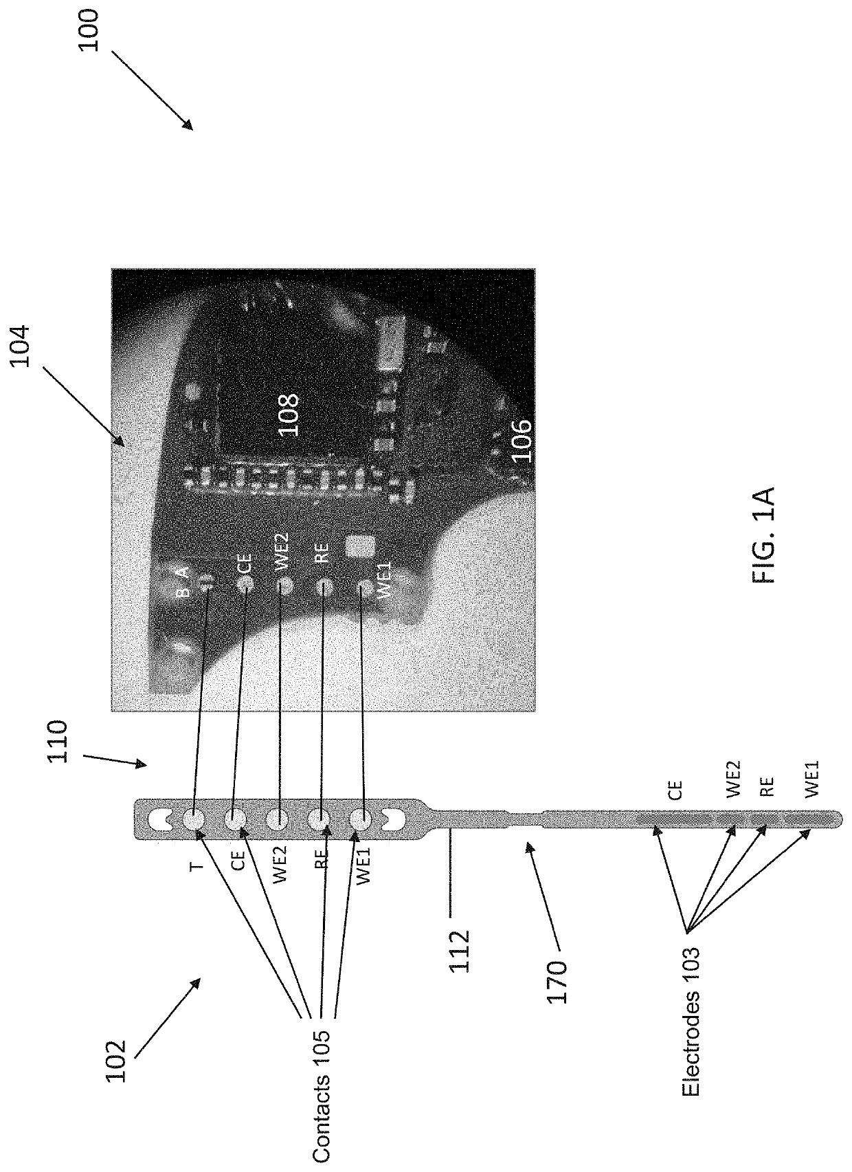
[0134]FIG. 4 illustrates an example wherein the sensing portion comprises one or more working electrodes WE1, WE2, a counter electrode CE, a reference electrode RE, and a plurality of contacts 105 including first contact T. FIGS. 5A-5C illustrate the electrical connection between the PCBA and the electrodes on the sensing portion when the elastomer mates, presses, or attaches the proximal end of the sensor portion onto the PCBA to make physical contact and electrical contact between the contacts 105 and the sensor connection contacts 118.

[0135]FIGS. 6A-6F illustrate example configurations of the sensor connections contacts 118 on the PCBA for connection to the electrodes CE, RE, WE1, WE2 on the sensing portion via contacts 105. FIG. 6A illustrates the sensor connection contacts 118 include a second contact A and a third contact B and the one or more processors comprise an application specific integrated circuit (ASIC) having an output connected to the sec...

second example

Contacts on Front Side of Sensor Portion

[0138]FIG. 6D illustrate another embodiment wherein a front side of the sensor portion faces and is in physical contact with the PCBA.

[0139]The sensor includes the contacts comprising a first contact (T) and the PCBA includes the sensor connection contacts comprising a second contact (A), a third contact (B), and a fourth contact (C). The PCBA further includes a first conductive track electrically 662 connecting the second contact (A) to the fourth contact (C).

[0140]The analyte sensor apparatus further includes an elastomer connector 150 comprising a second conductive track 650. The sensor portion 102 in operable connection with the PCBA comprises:[0141](1) the elastomer connector 150 pressing the first contact (T) into physical and electrical contact with the fourth contact (C).[0142](2) the second conductive track 650 electrically connecting to the second contact (A) to the third contact (B), and[0143](3) the first conductive track 662 and t...


PUM


Abstract

An analyte sensor apparatus including a sensing portion including one or more electrodes including a working electrode and one or more contacts for electrically connecting the sensor portion to control circuitry (e.g., a printed circuit board assembly, PCBA); and a circuit comprising the one or more contacts; wherein the circuit detects an electrical connection between the control circuitry without requiring exposure of the sensing portion to a fluid.

Description

TECHNICAL FIELD[0001]The invention relates to sensors and methods of fabricating the same.BACKGROUND OF THE INVENTION[0002]Electrochemical sensors are commonly used to detect or measure the concentrations of in vivo analytes, such as glucose. Typically in such analyte sensing systems, an analyte (or a species derived from it) is electro-active and generates a detectable signal at an electrode in the sensor. This signal is then correlated with the presence or concentration of the analyte within a biological sample. In some conventional sensors, an enzyme is provided that reacts with the analyte to be measured, the byproduct of the reaction being qualified or quantified at the electrode. In one conventional glucose sensor, immobilized glucose oxidase catalyzes the oxidation of glucose to form hydrogen peroxide, which is then quantified by amperometric measurements (e.g. change in electrical current) through one or more electrodes.[0003]It is desirable that glucose sensors be reliable ...

Claims


Application Information

Patent Timeline
Patent Type & Authority Applications(United States)
IPC IPC(8): A61B5/145A61B5/00A61B5/1495
CPCA61B5/14532A61B5/4839A61B5/1495A61B2560/0214A61B2562/227A61B2560/0223A61B2562/166A61B5/1486A61B2560/0276A61B2562/226A61B5/1473
Inventor CHOY, DAVID YUEH-HUAGARAI, ELLISTSANG, MELISSAPATEL, ANUJ M.
Owner MEDTRONIC MIMIMED INC
Why Eureka
Try Eureka