Systems and methods for tracking a tool in an ultrasound image

a tool and ultrasound imaging technology, applied in the field of ultrasound imaging, can solve the problems of missing parts of the tool from the ultrasound image, the tool is not aligned correctly, and the 2d imaging field is limited, so as to simplify facilitate the use of the tool, and facilitate the tracking of the tool

Pending Publication Date: 2022-02-10
KONINKLJIJKE PHILIPS NV
View PDF0 Cites 1 Cited by
  • Summary
  • Abstract
  • Description
  • Claims
  • Application Information

AI Technical Summary

Benefits of technology

[0018]By generating a 3D image based on a plurality of 2D images, it is possible to reduce the computational load on an ultrasound imaging system, whilst also simplifying the tracking of the tool.
[0019]Further, the updating of the 3D model using subsequently acquired 2D images allows the tool to be tracked as it moves and as the location from which the subsequent 2D images are taken moves. In this way, the method provides for convenient, accurate and fast guidance of the tool using a conventional 2D US transducer with minimal (or no) change required to the typical clinical work flow that may be used with any existing interventional tool and 2D ultrasound transducer.
[0020]In addition, the determining of the location of the tool with respect to the additional 2D ultrasound image allows the position of the transducer to be tracked relative to the position of the tool. Thus, as the transducer is manipulated, the relative position of the transducer to the tool may be known, thereby allowing more simple and accurate acquisition of the tool within the additional 2D ultrasound image. Further, as the additional 2D ultrasound image may include an area of interest, for example a tumor for biopsy, the tool may be guided to the area of interest using the relative location information.
[0021]Further, as the identifying of the tool is based only on the imaging data of the updated 3D ultrasound image, there is no requirement for a dedicated tool tracking system, such as a medical positioning system, in order to perform the method. Thus, the method may be performed by any ultrasound system without requiring additional specialist hardware, thereby increasing the availability and convenience of utilizing a tool tracking method.

Problems solved by technology

However, this mode of imaging has a number of drawbacks.
In particular, 2D imaging has a limited field of view; after a successful alignment and localization of the tool in the ultrasound image and while moving the tool or assessing the target, any undesired hand motion of the person conducting the procedure may cause misalignment of the tool and the ultrasound transducer such that parts of the tool are excluded from the ultrasound image.
This may lead to incorrect placement of the tool.
Furthermore, during the procedure, the focus of the operator may be diverted from treatment, as they may be distracted by searching for the tool in the ultrasound image.
External tool tracking systems also have a number of disadvantages, since they require additional equipment, which adds to the cost of the ultrasound imaging system.
Limiting the physician to the use of a specialized needle will likely add to the cost of the procedure.
However, these methods require the utilization of 3D ultrasound transducers, which are typically not readily available for use in needle guidance procedures and may add to the cost of a procedure.

Method used


Image

  • Systems and methods for tracking a tool in an ultrasound image
  • Systems and methods for tracking a tool in an ultrasound image
  • Systems and methods for tracking a tool in an ultrasound image

Examples


Embodiment Construction

[0066]The invention will be described with reference to the Figures.

[0067]It should be understood that the detailed description and specific examples, while indicating exemplary embodiments of the apparatus, systems and methods, are intended for purposes of illustration only and are not intended to limit the scope of the invention. These and other features, aspects, and advantages of the apparatus, systems and methods of the present invention will become better understood from the following description, appended claims, and accompanying drawings. It should be understood that the Figures are merely schematic and are not drawn to scale. It should also be understood that the same reference numerals are used throughout the Figures to indicate the same or similar parts.

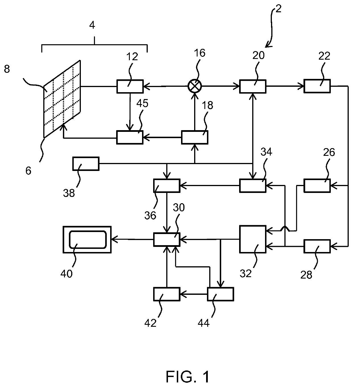
[0068]The invention provides a method for monitoring a location of a tool in an ultrasound image. The method includes acquiring a plurality of 2D ultrasound images by way of an ultrasound transducer, wherein at least one o...


PUM


Abstract

The invention provides a method for monitoring a location of a tool in an ultrasound image. The method includes acquiring a plurality of 2D ultrasound images by way of an ultrasound transducer, wherein at least one of the plurality of 2D ultrasound images comprises a part of the tool and generating a 3D ultrasound image from said plurality of 2D ultrasound images. A first location of the tool is then identified within the 3D ultrasound image. An additional 2D ultrasound image, and location information relating to the location of the ultrasound transducer during capture of the additional 2D ultrasound image, is then acquired and the 3D ultrasound image updated based on the additional 2D ultrasound image and the location information. A location of the tool with respect to the additional 2D ultrasound image is then identified within the updated 3D ultrasound image based only on imaging data of the updated 3D ultrasound image.

Description

FIELD OF THE INVENTION[0001]The present invention relates to the field of ultrasound imaging, and more specifically to the field of tracking a tool within an ultrasound image.BACKGROUND OF THE INVENTION[0002]Ultrasound imaging is one of the most popular imaging systems for tool guidance applications. Ultrasound imaging may be used to image tools such as needles, laparoscopes, stents, and radioactive seeds used for brachytherapy. For example, ultrasound imaging may be used for needle guidance in anesthesiology, tissue ablation or for biopsy guidance, since needles are used to take tissue samples, and to deliver medicine or electrical energy to the targeted tissue inside a patient's body. During these procedures, visualization of the needle and its tip is very important in order to minimize risk to the patient and improve health outcomes.[0003]Typically, 2D ultrasound guidance is used to visualize a tool while a procedure is being conducted. However, this mode of imaging has a number ...

Claims


Application Information

Patent Timeline
Patent Type & Authority Applications(United States)
IPC IPC(8): A61B8/08A61B8/00A61B90/00
CPCA61B8/0841A61B8/483A61B2090/367A61B90/36A61B2562/0219A61B8/466A61B34/20A61B2034/2065A61B2090/378A61B2034/2048A61B2017/3413A61B8/5223G01S15/8993
Inventor MIHAJLOVIC, NENADPOURTAHERIAN, ARASHVAN BRUGGEN, MICHEL PAUL BARBARANG, GARY CHENG-HOW
Owner KONINKLJIJKE PHILIPS NV
Why Eureka
Try Eureka