Method and apparatus for determining the directional frequency response of an arrangement of transducer elements

Pending Publication Date: 2022-02-24
THE SEC OF STATE FOR DEFENCE IN HER BRITANNIC MAJESTYS GOVERNMENT OF THE UK OF GREAT BRITAIN & NORTHERN IRELAND
View PDF0 Cites 0 Cited by
  • Summary
  • Abstract
  • Description
  • Claims
  • Application Information

AI Technical Summary

Benefits of technology

The invention provides a method for determining the performance of a sensor array over a broad frequency range. This method is particularly useful for applications involving audio signals. The method involves simulating the locations of the arrangement of transducer elements and applying a Fourier Transform to convert the simulation of locations into corresponding frequency response values. The use of a periodic spatial function can further improve the efficiency of the conversion process. The directional frequency response of the arrangement of transducer elements can be determined by controlling the beamforming direction. This method allows for efficient and accurate determination of the directional frequency response of an arrangement of transducer elements.

Problems solved by technology

However, it can be time-consuming, inconvenient and expensive to construct an array to determine the operational performance.
This approach may be especially inconvenient and costly in situations where it would be preferable to compare the performance of multiple arrays or for particular applications, such as, in the field of radio astronomy where the radius of an array may span several kilometres or more.

Method used


Image

  • Method and apparatus for determining the directional frequency response of an arrangement of transducer elements
  • Method and apparatus for determining the directional frequency response of an arrangement of transducer elements
  • Method and apparatus for determining the directional frequency response of an arrangement of transducer elements

Examples


first embodiment

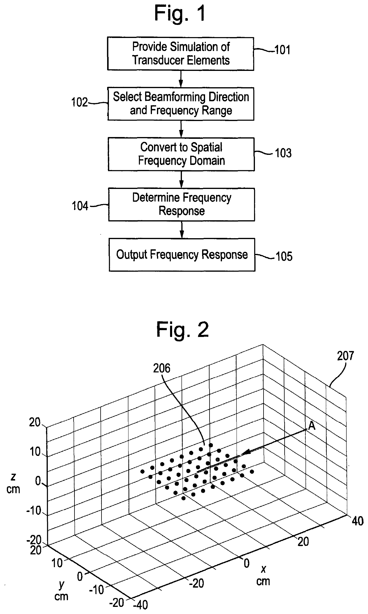
[0077]With reference to FIG. 1, in the method of determining the directional frequency response of an arrangement of transducer elements, a simulation of the locations of an arrangement of transducer elements is provided 101 as a periodic spatial function. The transducer elements, having a two-dimensional arrangement, are located in an xy plane of the spatial domain, having spatial coordinates x,y. The transducer elements could equally have a one-dimensional or a three-dimensional arrangement. The periodic spatial function is determined by sampling the sensor space with an infinite grid of lattice points. A sinc filter is used as an anti-aliasing filter to determine appropriate gain values at each of the lattice points due to the proximity, or otherwise, of any transducer elements.

[0078]A beamforming direction and frequency range are provided appropriate to the intended application 102, being to determine the directional frequency response of an arrangement of microphones for detect...

second embodiment

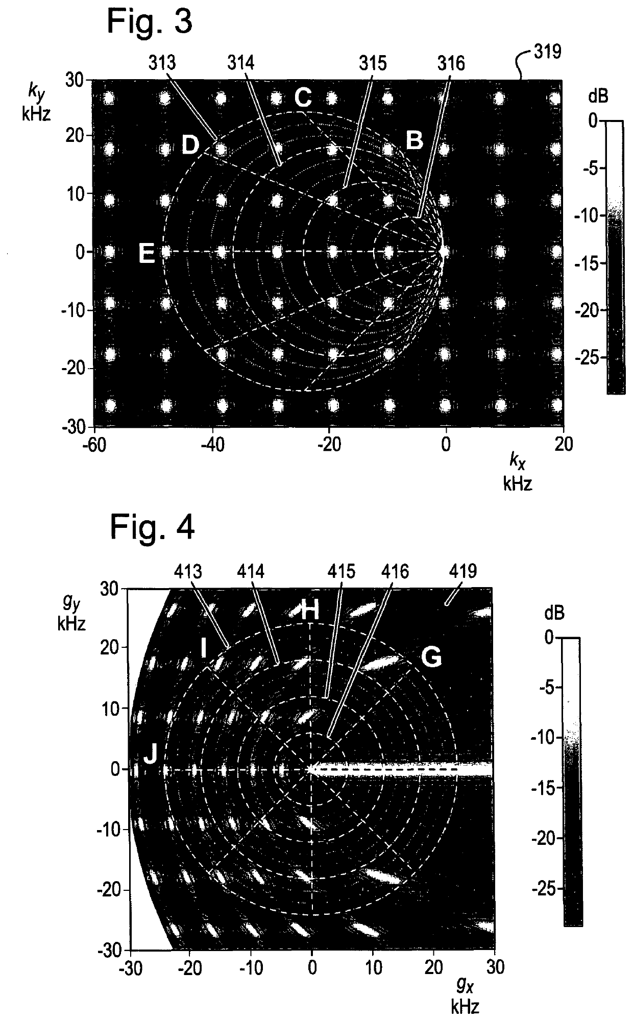
[0085]With reference to FIG. 2, in the method of determining the frequency response of an arrangement of transducer elements, 48 microphone transducer elements 206 are arranged in two dimensions in the xy plane of the spatial domain 207. Each of the 48 microphones is configured to receive sound in the selected frequency range of 0 Hz to 24 kHz. The beamforming direction is specified relative to the arrangement of transducer elements, in the positive x direction, to detect signals travelling in the negative x direction as indicated by arrow A. The frequency range of 0 Hz to 24 kHz is selected. Equally, other beamforming directions and frequency ranges may be selected.

[0086]The 48 microphones are equidistantly spaced at 36 mm in the x direction and 39 mm in they direction, and, for the purposes of determining the simulation of their locations, are defined within a sensor space having dimensions of 3.6 m×3.6 m. The resulting periodic spatial function of the arrangement of 48 microphone...

fourth embodiment

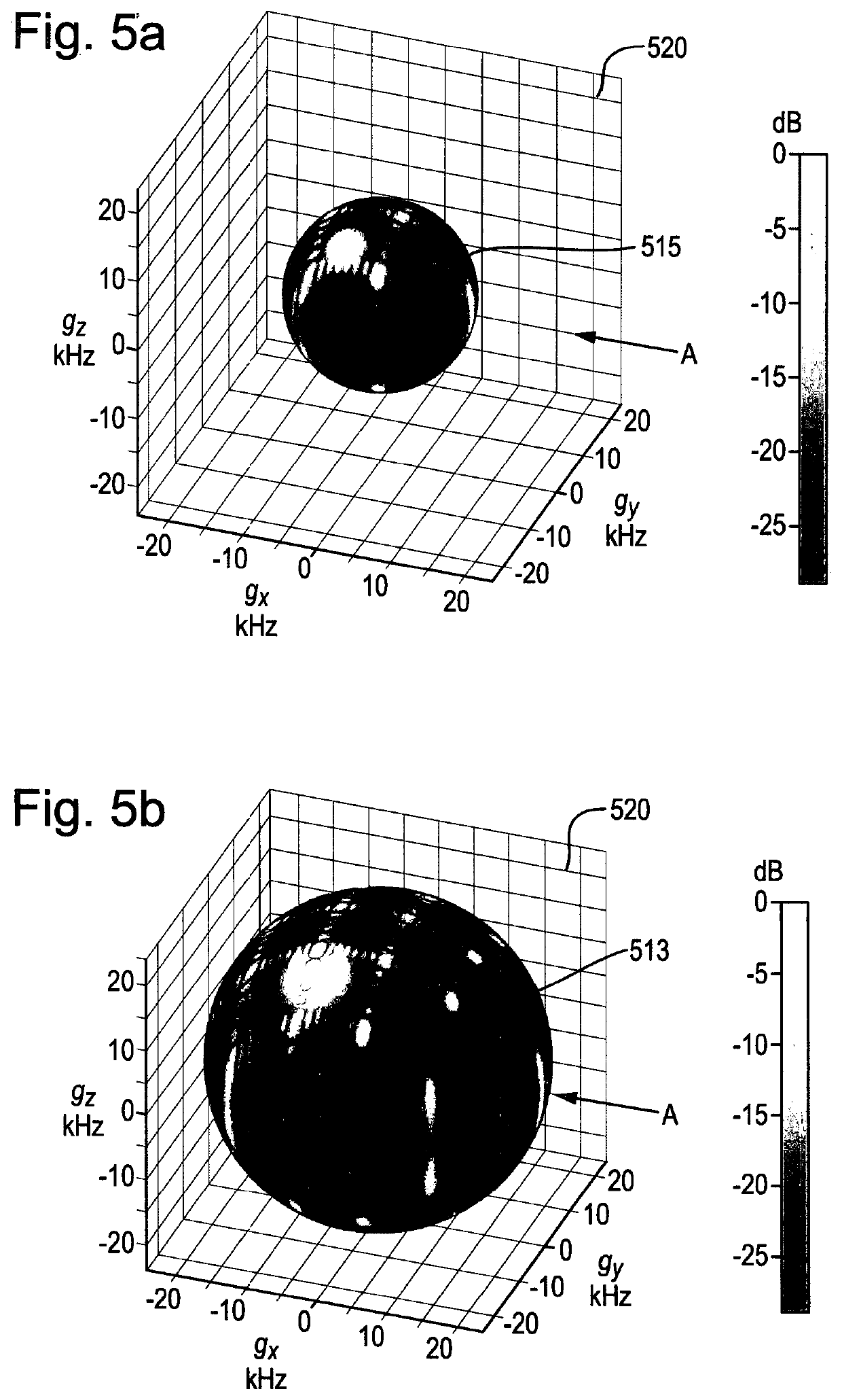
[0097]With reference to FIGS. 7a and 7b, in the method of determining the frequency response of an arrangement of transducer elements, seventeen microphone transducer elements 706 are arranged in two-dimensional concentric rings in the xy plane of the spatial domain 707. Each of the seventeen microphones is configured to receive sound in the selected frequency range of 0 Hz to 12 kHz. The beamforming direction is specified relative to the arrangement of transducer elements 706, in the positive x direction, to detect signals travelling in the negative x direction as indicated by arrow Z. The frequency range of 0 Hz to 12 kHz is selected. Equally, other beamforming directions and frequency ranges may be selected.

[0098]The seventeen microphones 706 are arranged in three concentric rings, and, for the purposes of determining the simulation of their locations, are defined within a sensor space having dimensions of 7.2 m×7.2 m. The resulting periodic spatial function of the arrangement of...


PUM


Abstract

A method for determining the directional frequency response of an arrangement of transducer elements. The method comprises providing a simulation of locations of the transducer elements, in the spatial domain; providing a beamforming direction and a frequency range; converting the simulation of locations from the spatial domain into corresponding frequency response values in a spatial frequency domain, such that, for each frequency of a plurality of frequencies in the frequency range, a spatial frequency contour is defined, each of the spatial frequency contours intersecting at the origin; determining the frequency response by applying a transformation to the frequency response values for the provided beamforming direction and frequency range, translating the spatial frequency domain into a modified frequency domain, wherein the contours avoid intersecting; and outputting the frequency response. There is further provided a data processing device adapted to perform the method, a computer program, and a computer-readable medium.

Description

TECHNICAL FIELD OF THE INVENTION[0001]The invention relates to a computer-implemented method of determining the frequency response as a function of direction of an arrangement of transducer elements and a data processing device comprising a processor adapted to perform the method. The invention also relates to a computer program, and a computer-readable medium comprising instructions, which, when executed by a computer, cause the computer to carry out the method.BACKGROUND TO THE INVENTION[0002]Sensor arrays, such as those configured to transmit and / or receive electromagnetic or acoustic signals, typically comprise a plurality of sensor elements having a particular spatial arrangement. Sensor elements within sensor arrays are often combined using beamforming techniques to enable the directional transmission or reception of a signal. In general, the directional response of a sensor array typically varies according to, for example, the number of sensor elements in the array, and the c...

Claims


Application Information

Patent Timeline
IPC IPC(8): H04B7/08H04B7/06G01N29/26G01S7/54G01N29/22H04R3/00
CPCH04B7/086H04B7/0617G01N29/262H04R29/002G01N29/221H04R3/005G01S7/54G10K11/34G01N2291/106G01N29/4472G01N29/34G01N29/30H04R2201/401H04R29/005G01S3/8083G06F30/20
Inventor SINGLETON, GREGORYGLASSON, PHILIP HENRY
Owner THE SEC OF STATE FOR DEFENCE IN HER BRITANNIC MAJESTYS GOVERNMENT OF THE UK OF GREAT BRITAIN & NORTHERN IRELAND
Why Eureka
Try Eureka