
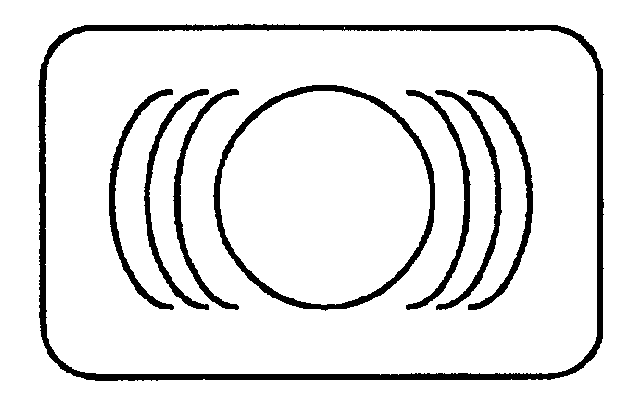
Data card with a full circular track for alignment and amplitude calibration

a data card and amplitude calibration technology, applied in the direction of digital signal error detection/correction, magnetic tape recording, instruments, etc., can solve the problems of less efficiency, less time, and less processing efficiency, and achieve uniform data storage density, convenient centering, and enabling efficient positioning operations

Inactive Publication Date: 2005-08-23
DCARD
View PDF10 Cites 8 Cited by
  • Summary
  • Abstract
  • Description
  • Claims
  • Application Information

AI Technical Summary

Benefits of technology

[0010]Therefore, an object of the present invention is to provide a data storage-card drive system with single pickup head moving above the data-storage card in rotational movement. The data read-write functions are enabled only for arc-segments of the rotational movement guided by servo data written to servo sectors on the data arc with proper offsets. Also, the data tracks are arranged as plurality of parallel arcs, e.g., half-circles. At least one special full circle data track is provided for conveniently determining a central axis of the data card and for obtaining a measurement of average amplitude such that the above mentioned difficulties and limitations encountered in a regular data card can be overcome.
[0012]Another object of the present invention is to provide a data-storage card drive system for performing the data access tasks over a data storage medium surface, which has uniform data storage density. A new configuration of data-tracks formed as parallel arc or arc-segments, e.g., semi-circular data track, is implemented such that all data tracks have substantially the same length for data storage and the data bits are stored with uniform density. In the meantime, at least one full circle data track is formed on the data card for enabling efficient operations of positioning the data card and obtaining a measurement of average signal amplitude for signal calibration.

Problems solved by technology

The process is less efficient and may be time consuming thus preventing the operations of reading data from or writing data to the data card in a timely manner.
Again, for a data card that has multiple data arcs, such calibration process may required data signals from multiple data arcs and thus would be less efficient and taking up longer times and slowing down the initialization of data reading and writing operations.
Due to these reasons, less efficient operation and slower initialization may often be encountered when regular data card formed with multiple parallel data arcs are implemented.
The concentric data track configuration often presents a problem that the data-bit density varies between the outer tracks and the inner tracks.
A more complicate servo control system implemented with more complex signal-processing algorithms is required due to the variations of data storage density between different data tracks.
Such variation may also cause difficulties and complications in processing the data.
Higher error rates may incur due to these variations between the inner tracks and the outer tracks.
However, the inefficiency and complexities of the operations to position the card and to calibrate the signal amplitude still present as technical difficulties to those of ordinary skill in the art yet to be resolved.

Method used


Image

  • Data card with a full circular track for alignment and amplitude calibration
  • Data card with a full circular track for alignment and amplitude calibration
  • Data card with a full circular track for alignment and amplitude calibration

Examples


Embodiment Construction

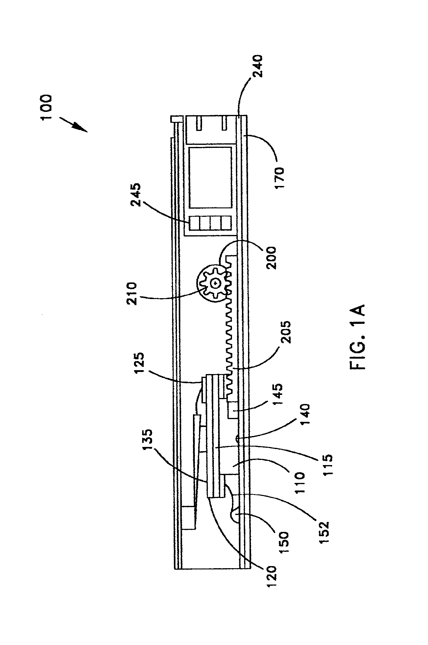
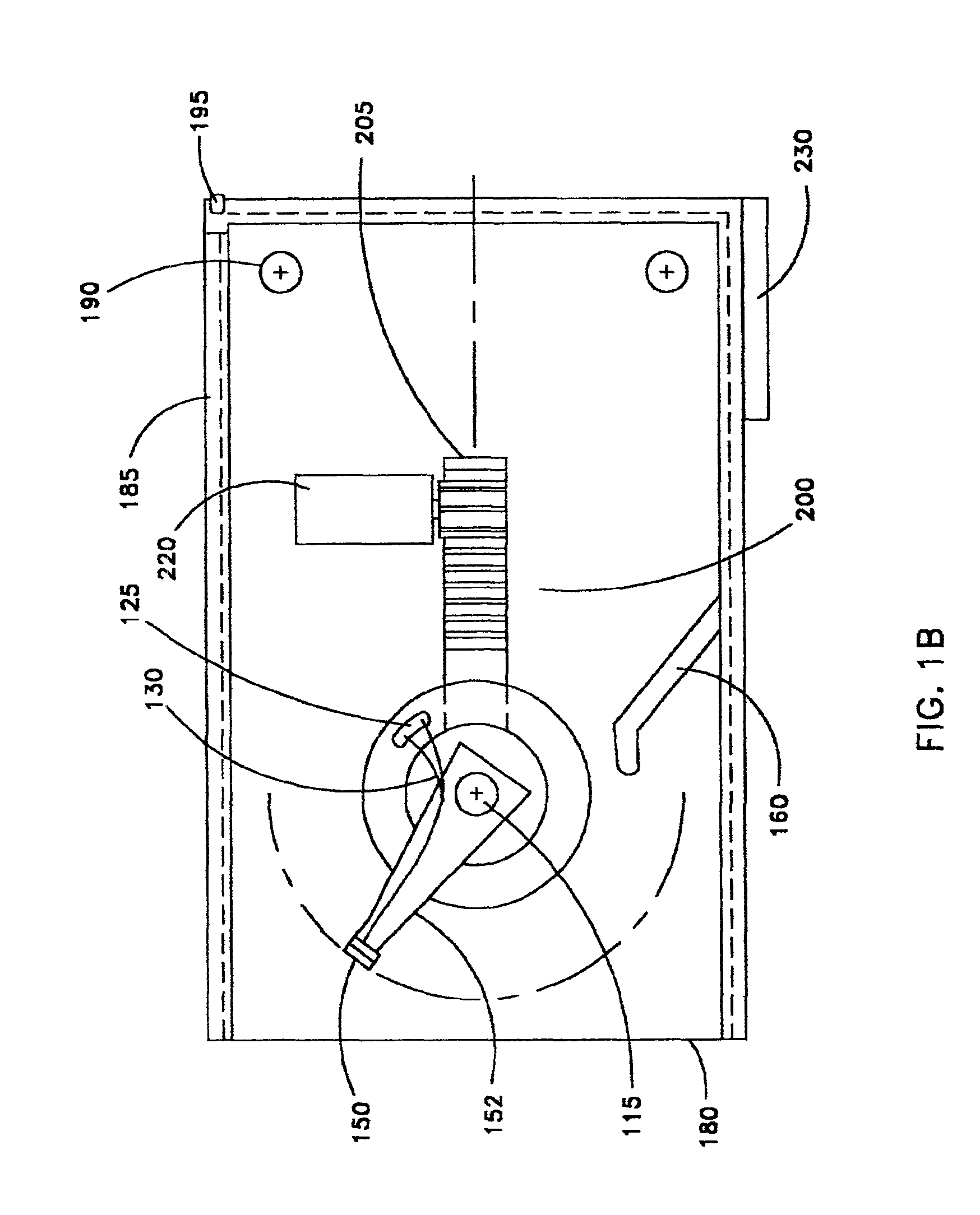
[0033]FIGS. 1A and 1B show a cross sectional view and a top view respectively of a data-card drive 100 of the present invention. The data-card drive 100 can be configured for reading and writing data-cards of different sizes, e.g., a PCMCIA type card or common credit card size. The data-card can also be of different shapes such as a square, a rectangular, a circular disk, or a card with straight and parabolic edges or different types of arc-edges. The data-card drive 100 includes a motor 110, e.g., a DC brushless motor. The motor 110 is provided to operate at a low speed to conserve battery power, at high speeds to achieve fast data access time. The motor 110 is further provided to function at two different modes, i.e., a sleep mode when not being deployed, and a wake up mode for normal data access operations. The motor 110 is mounted on a carriage 115 with a pickup head assembly mounted to the motor rotating shaft assembly. Half of a magnetic transformer, 120-1 which can either bei...


PUM

PropertyMeasurementUnit
radiusaaaaaaaaaa
distanceaaaaaaaaaa
magnetic fluxaaaaaaaaaa

Abstract

This invention discloses a flat data storage medium that includes a plurality of substantially parallel data arc-segments. The data arcs further include at least one full circle data track provided for obtaining a measurement of an average amplitude of data signals over the full circle data track for calibrating a pickup head implemented for reading data from the data arc-segments. This invention further discloses a data storage system for accessing data stored in a data storage medium. The data storage system includes dynamic head loading / unloading system that includes a handle for pushing a linkage connected to the handle for loading and unloading the data storage medium to an engaged and disengaged positions relative to a pickup head for accessing data disposed on the data storage medium. The dynamic head loading / unloading system further includes a locking mechanism for automatically locking the data storage medium inside the data storage system when the linkage is disposed at an engaged-position. The dynamic head loading / unloading system further includes a data-storage medium orientation-selection for cooperating and adapting the data storage medium inside the data storage system only when the data storage medium is inserted into the data storage system in a predefined orientation.

Description

[0001]This Application is a Continuation-in-Part Application (CIP) of a previously filed Provisional Application No. 60 / 081,257 filed on Apr. 9, 1998 and a Formal application Ser. No. 09 / 289,427 filed on Apr. 9, 1999, now U.S. Pat. No. 6,574,776 by one of a common inventors of this Patent Application.BACKGROUND OF THE INVENTION[0002]1. Field of the Invention[0003]This invention relates generally to systems and method for reading data from and writing data to data storage medium by employing the magnetic or optical recording technology. More particularly, this invention is related to a data card provided with at least one full circle data track among a group of data arc segments for card position alignment and signal amplitude calibration.[0004]2. Description of the Prior Art[0005]For a data card formed with multiple data arc segments, there is a need to determine the central axis of the data card to precisely position the data card for reading and writing data. As the data card has ...

Claims


Application Information

Patent Timeline
Patent Type & Authority Patents(United States)
IPC IPC(8): G11B5/80G11B21/08G11B7/26G11B20/18G11B5/00G11B5/008G11B21/02G11B21/04G11B25/04G11B17/04G11B7/007G11B7/09G11B5/58G11B5/596G06K19/06G06K7/08G11B7/12G11B7/0033G11B7/00G11B7/085G11B5/53
CPCG06K7/084G06K19/06009G06K19/06196G11B5/00G11B5/00804G11B5/00808G11B5/58G11B5/59633G11B5/80G11B7/0033G11B7/007G11B7/0857G11B7/08576G11B7/0938G11B7/12G11B7/26G11B17/0408G11B20/1833G11B21/02G11B21/04G11B21/081G11B25/04G11B25/046G11B5/53
Inventor KING, FRANCIS K.LIU, JEFFREY F.MAO, SHAND-LING
Owner DCARD
Learn More