
Systems and methods of improved plant cultivation and elongate airflow assembly for the same

a technology of airflow and plant cultivation, which is applied in the direction of greenhouse cultivation, machines/engines, liquid fuel engines, etc., can solve the problems of unsuitable for regulating air circulation, inconsistent, moldy, mildew, etc., and achieve the effect of optimizing growing conditions, improving plant cultivation, and improving the growth conditions of an environmen

Active Publication Date: 2022-03-10
AIRFIXTURE
View PDF3 Cites 0 Cited by
  • Summary
  • Abstract
  • Description
  • Claims
  • Application Information

AI Technical Summary

Benefits of technology

The present invention is about improving plant cultivation by using an elongated airflow assembly to provide controllable and selectable air flow to plants. The elongated airflow assembly can create a consistent sheet of air that is directed at a uniform velocity across a wide area, which helps plants absorb water better and grow faster. It also prevents high humidity micro-climates that can lead to mold and pests. The elongated airflow assembly is easy to use and compatible with different growing environments. The technical effects of the invention include improved growing conditions for plants and increased efficiency in plant cultivation.

Problems solved by technology

These HVAC systems and industrial fans provide high volumes of air flow, but do not do so at a consistent velocity.
As a result, some plants get too much air (e.g., over 250 ft / min velocity), which creates wind burn, and some plants do not get enough air, which can result in high humidity micro-climates that can lead to mold, mildew, and rot.
Consequently, the air flow to plants located in the same or different spaces of the indoor grow environment is non-uniform, inconsistent, and / or unpredictable.
As such, the HVAC systems and fans discussed by the prior art are not capable of providing controllable and / or selectable air flow and thus are not suitable for regulating air circulation in a localized manner to optimize growing conditions for one or more plants being grow in indoor environments.
Additionally, the HVAC systems and fans discussed by the prior art may be unsuitable for a variety of different grow environments for other reasons, namely they are typically difficult to clean, are difficult to move, and / or require high voltage power.
For instance, when one or more plants of a grow environment are contaminated, these HVAC systems and fans may be problematic and if improperly maintained and / or cleaned, could contribute to a spreading of contamination and / or recontamination.
Moreover, the prior art HVAC systems distribute air flow from exit vents that have fixed locations in walls, floors, and / or ceilings of a room and thus relocating the exit vents and / or adding additional exit vents so that air flow is distributed from a different location generally requires substantial undertakings and / or costs.
Some of the prior art fans (e.g., ceiling fans) have fixed locations and thus are deficient in this same way.
While the other prior art fans (e.g., floor-standing fans) may be moved from one location to another, a size of these fans and / or spatial constrains of a grow environment (e.g., minimal distance separating one or more grow racks) may prohibit the fans from being moved to more desirable locations.
Notwithstanding, even if these prior art fans were moveable to such locations, they would likely still be unsuitable for a variety of different grow environments since the volume and air velocity of the air flow widely inconsistent across the air flow regardless of their location.
Further, due to their high voltage requirements, the prior art HVAC systems and fans may be unsafe when operated around water and / or in damp or wet environments, like, for example, while watering plants.
Accordingly, the HVAC systems and fans discussed by the prior art are not easily useable and compatible and thus are not adaptable for improving plant cultivation in a variety of different growing environments.
As a result, these prior art devices are not capable of providing controllable and / or selectable air flow or of being detachably mounted and / or repositioned on a grow rack and, therefore, are not suitable for regulating air circulation of an indoor grow environment in a localized manner that optimizes growing conditions or for improving plant cultivation in a variety of different grow environments.

Method used


Image

  • Systems and methods of improved plant cultivation and elongate airflow assembly for the same
  • Systems and methods of improved plant cultivation and elongate airflow assembly for the same
  • Systems and methods of improved plant cultivation and elongate airflow assembly for the same

Examples


Embodiment Construction

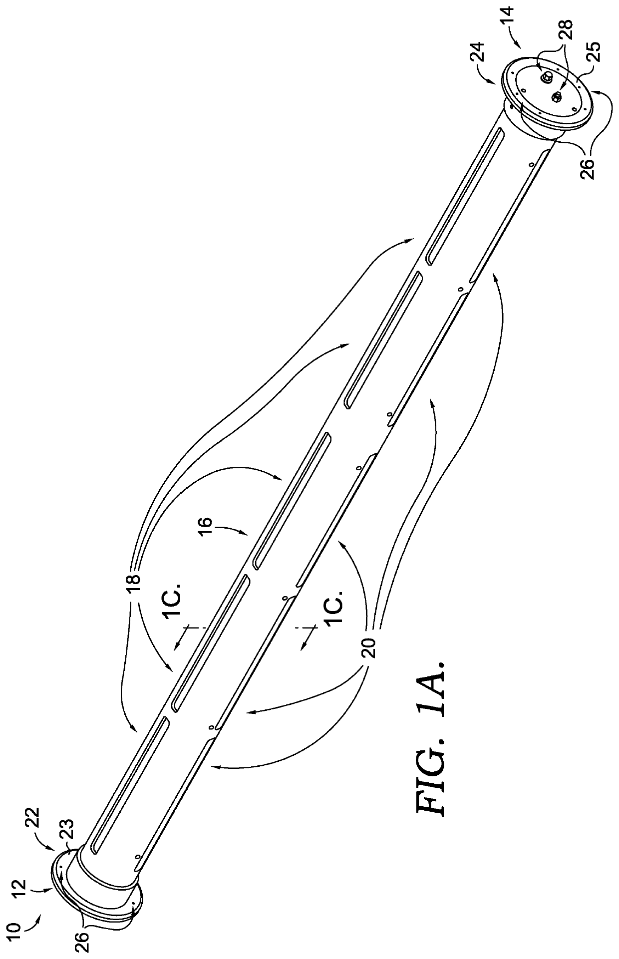
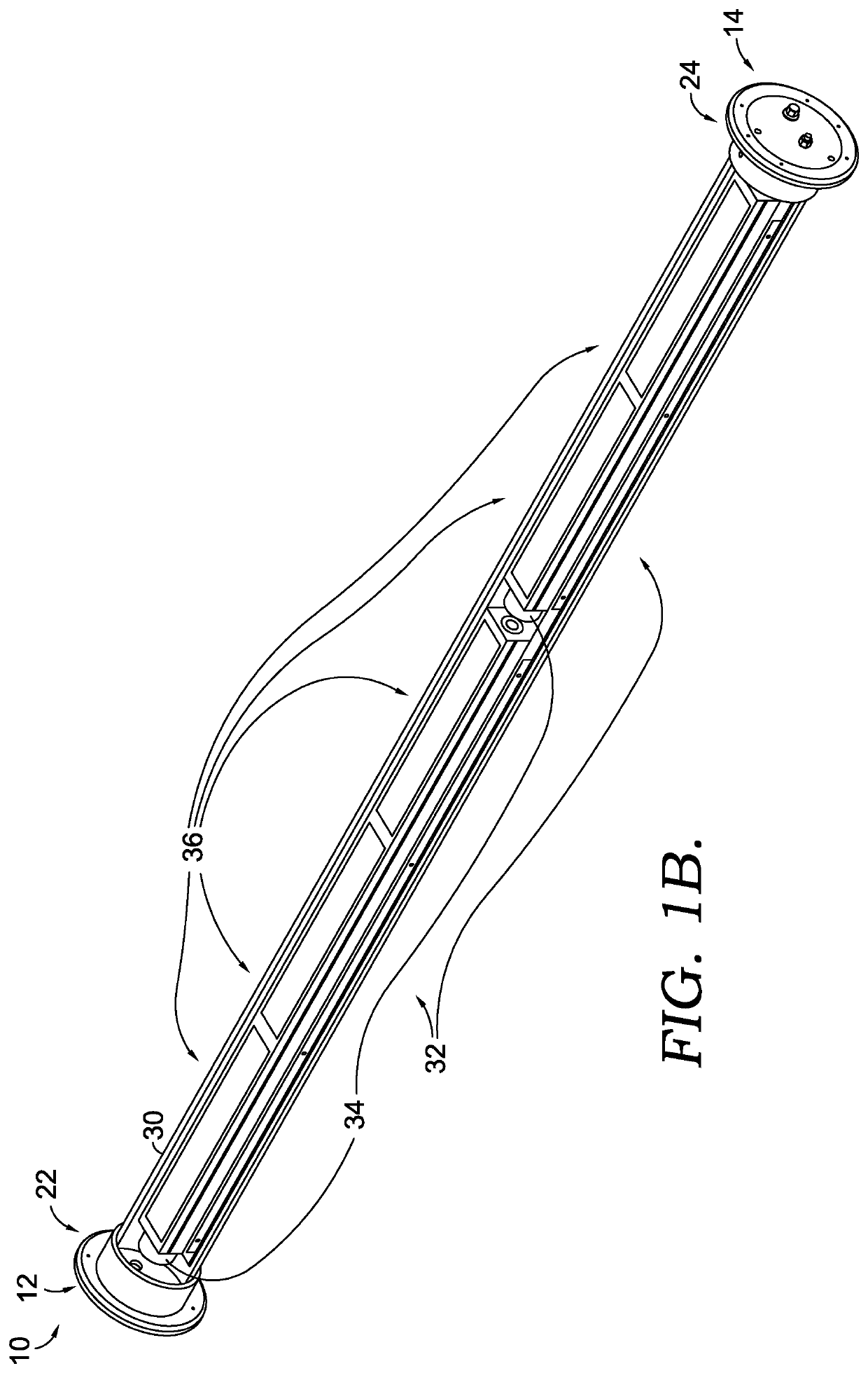
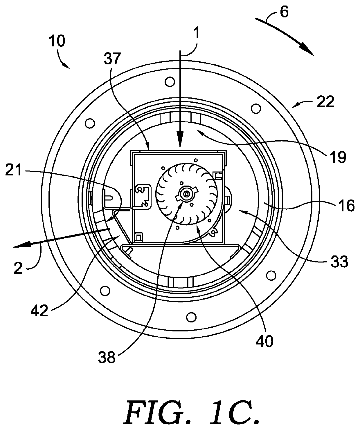
[0026]Referring now to the drawings in more detail, and initially to FIG. 1A, which is a top right, front perspective view of an example elongate airflow assembly 10 including a first end 12, a second end 14 opposite the first end 12, and a housing 16 extending between the first and second ends 12, 14. The housing 16 is cylindrically shaped and is configured to be connected with a first end cap 22 at the first end 12 and a second end cap 24 at the second end 14. In other examples, the housing 16 may have a shape that includes straight edges such that the housing has a cross sectional shape of a rectangle, pentagon, hexagon, heptagon, octagon, enneagon, decagon, and the like. Both of the first and second end caps 22, 24 are configured to have a shape that is capable of receiving the housing 16, and in this example, the first and second end caps 22, 24 include a flat circular portion and a cylindrical portion extending therefrom that receives the housing 16. The first and second end c...


PUM


Abstract

An elongate air delivery assembly having a housing extending between two end caps. The housing includes a plurality of exit vents from which airflow is provided in a consistent sheet at a uniform velocity, and the housing is rotatable about a central longitudinal axis to change a direction of the airflow. A method of improving plant cultivation includes positioning one or more elongate air delivery systems adjacent rows of plants such that the sheet of air generated by the elongate air delivery system is directed horizontally across the plants underneath their plant canopy.

Description

CROSS-REFERENCE TO RELATED APPLICATIONS[0001]This application claims the benefit of U.S. Provisional Application No. 63 / 076,276 filed Sep. 9, 2020, and title “SYSTEMS AND METHODS OF IMPROVED PLANT CULTIVATION AND ELONGATE AIR ASSEMBLY FOR THE SAME,” the contents of which are incorporated herein by reference in the entirety.STATEMENT REGARDING FEDERALLY SPONSORED RESEARCH OR DEVELOPMENT[0002]Not applicable.BRIEF SUMMARY OF THE INVENTION[0003]The present invention generally relates to improvements in plant cultivation. More particularly, this invention relates to systems and methods, as well as an elongate airflow assembly, for optimizing and / or improving growing conditions of an environment in which plants are grown. The systems and methods may utilize the elongate airflow assembly, which may be configured to provide controllable and / or selectable air flow (e.g., adjustable direction and / or air velocity) to one or more plants. In one embodiment the elongate airflow assembly provides ...

Claims


Application Information

Patent Timeline
Patent Type & Authority Applications(United States)
IPC IPC(8): A01G9/24F04D17/16F04D29/42F04D29/46
CPCA01G9/24F04D29/462F04D29/4226F04D17/16F04D17/04F04D29/626A01G9/246Y02A40/25
Inventor MEGERSON, JAMES E.MCQUEENY, JR., MICHAEL J.CHO, SUWAN
Owner AIRFIXTURE
Learn More