Lead-free solder composition

Active Publication Date: 2022-03-24
APTIV TECH LTD
View PDF7 Cites 0 Cited by
  • Summary
  • Abstract
  • Description
  • Claims
  • Application Information

AI Technical Summary

Benefits of technology

The patent text describes a solder alloy that includes specific amounts of indium, zinc, silver, and tin. The solder alloy can have a variety of different compositions, with the most common being 15% to 28% indium, 5% to 20% zinc, 1% to 6% silver, and 54% to 79% tin. The solder alloy can also contain other elements such as copper, which can be present in amounts of 1% to 3%. The technical effect of this patent is to provide a solder alloy with specific compositions that can be used for various applications such as electronics assembly.

Problems solved by technology

Physical properties of high indium-based solders provided better resistance to cracking than leaded solder but was cost prohibitive in regular production.
The higher cost of indium versus other solder alloy metals has been a barrier to wider application of indium-based lead-free solder.
However, this alternative still has drawbacks of causing some glass cracking, a narrow processing temperature window, additional process steps of preheating, controlled cooling of the glass, and a need for silver plating to improve electrical conductivity.

Method used


Image

  • Lead-free solder composition
  • Lead-free solder composition
  • Lead-free solder composition

Examples


Embodiment Construction

[0037]Reference will now be made in detail to embodiments, examples of which are illustrated in the accompanying drawings. In the following detailed description, numerous specific details are set forth to provide a thorough understanding of the various described embodiments. However, it will be apparent to one of ordinary skill in the art that the various described embodiments may be practiced without these specific details. In other instances, well-known methods, procedures, components, circuits, and networks have not been described in detail so as not to unnecessarily obscure aspects of the embodiments.

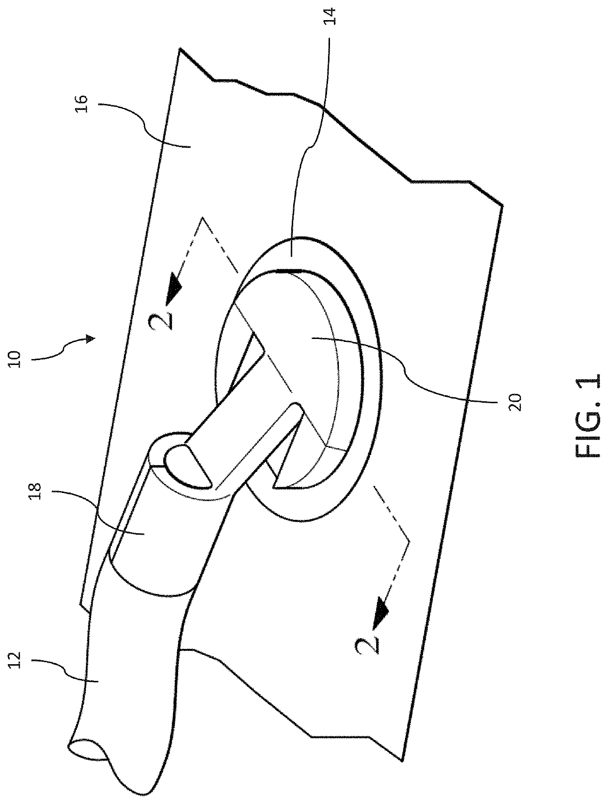
[0038]FIG. 1 illustrates an example of an electrical connector 10 that is adapted to make an electrical connection between a wire electrical cable 12 and a conductive contact pad 14 on a planar surface 16, such as a glass windshield or rear window of an automobile. This connector may be used to establish electrical connections from the vehicle's wiring system to circuits, such as he...


PUM

PropertyMeasurementUnit
Fractionaaaaaaaaaa
Fractionaaaaaaaaaa
Fractionaaaaaaaaaa

Abstract

An electrical connector includes a first layer having a first coefficient of thermal expansion and a second layer overlaying the first layer having a second coefficient of thermal expansion. A first difference between the first coefficient of thermal expansion and a coefficient of thermal expansion of glass is greater than a second difference between the second coefficient of thermal expansion and the coefficient of thermal expansion of glass. The electrical connector further includes a layer of a solder alloy having about 15% to 28% indium by weight, about 5% to 20% zinc by weight, about 1% to 6% silver by weight, and at least 36% tin by weight. The solder layer is disposed on at least a portion of the second layer.

Description

TECHNICAL FIELD OF THE INVENTION[0001]The present invention relates generally to lead-free solder compositions and more particularly to lead-free solder compositions suitable for electrical terminals attached to an electrical contact pad, for example on a glass surface.BACKGROUND OF THE INVENTION[0002]Lead-based solder has been used for soldering electrical terminals to silver grids printed on automotive glass since the heated grid was developed. Indium-based solders were used under special circumstances on annealed glass windshields where the product was particularly sensitive to cracking. Physical properties of high indium-based solders provided better resistance to cracking than leaded solder but was cost prohibitive in regular production.[0003]In the year 2000, the European Union issued a directive to prohibit the use of lead in automotive glass applications after 2003. Although lead would be exempted from this directive for many years, some OEMs and glass suppliers were proacti...

Claims


Application Information

Patent Timeline
IPC IPC(8): B23K35/26C22C30/04C22C30/06
CPCB23K35/262C22C30/06C22C30/04B23K35/26C22C13/00Y10T428/12597Y10T428/12715Y10T428/12722B23K2103/12B23K2103/54B23K2103/02
Inventor ANTAYA, STEPHEN C.FALK, WILLIAMAMALFITANO, JUSTINDATTA, AMIT
Owner APTIV TECH LTD
Why Eureka
Try Eureka