
Bootstrap pre-charge circuit in totem-pole power factor correction converter

Pending Publication Date: 2022-03-24
MURATA MFG CO LTD
View PDF0 Cites 1 Cited by
  • Summary
  • Abstract
  • Description
  • Claims
  • Application Information

AI Technical Summary

Benefits of technology

The present invention provides a power factor correction converter with a pre-charging circuit that charges a bootstrap capacitor after an AC input voltage has a negative half-cycle. This allows for improved power factor correction and reduced energy waste. The converter can operate as a single channel or a dual channel converter, and the method for controlling the converter allows for efficient and effective power factor correction. The technical effects of the invention include improved power factor correction, reduced energy waste, and improved control of power factor correction converter.

Problems solved by technology

If a bootstrap circuit is used in a totem-pole topology for the high-side gate driver, there may be problems when starting the PFC converter in the negative portion of the AC cycle, unless a capacitor in the bootstrap circuit is pre-charged.
Bootstrapping the high-side power supply input without pre-charging the bootstrap capacitor may create significant delays of a few milliseconds if the channel is engaged in the negative half-cycle of the input AC voltage.
This is problematic under certain conditions.
The result is a further drop in the converter output voltage, which may cause the next converter stage to shut down due to an under-voltage input condition.
Such operational behavior limits the ride-through capability of the converter.
Another condition that may cause a delay problem is during a transient in the load.
A delay in the boost operation of the second channel will cause the output voltage tracking error to increase.
However, overstressing one channel may cause problems such as reaching the maximum allowed current.
The transient response of the converter also suffers because a sudden engagement of the second channel during a positive portion of the AC input voltage produces an overshoot in the output voltage due to previous power compensation from the control circuitry.
Significant overshoot may set various warning flags due to an overvoltage condition.
The control circuitry will eventually correct for this issue and set the power delivered to output at the correct value, but the overall transient response and performance of the converter is deteriorated.
On the other hand, using an existing power supply with a bootstrap circuit is a simpler alternative, but suffers from the limitations discussed above.

Method used


Image

  • Bootstrap pre-charge circuit in totem-pole power factor correction converter
  • Bootstrap pre-charge circuit in totem-pole power factor correction converter
  • Bootstrap pre-charge circuit in totem-pole power factor correction converter

Examples


Embodiment Construction

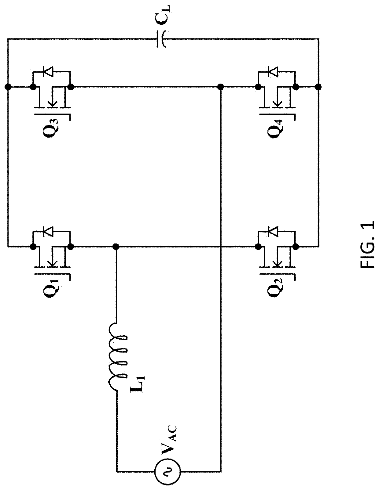
[0024]FIG. 1 is a circuit diagram of a single-channel TPPFC boost converter according to a preferred embodiment of the present invention. In FIG. 1, the single-channel TPPFC converter includes an AC voltage input VAC, an inductor L1, switches Q1 and Q2 that can act like switching devices to control the flow of current, switches Q3 and Q4 that can act as line transistors in that the switches Q3 and Q4 are turned on and off at the input line frequency, usually about 50 Hz to about 60 Hz to mimic diodes, and a load capacitance CL. The switches Q1 and Q2 are connected in cascade, and the switches Q3 and Q4 are connected in cascade. The inductor L1 is connected between a terminal of the AC voltage input VAC and a node between the switches Q1 and Q2. The other terminal of the AC voltage input VAC is connected to a node between the switches Q3 and Q4. The load capacitance CL is connected in parallel with the switches Q1 and Q2 and with the switches Q3 and Q4. The switches Q1, Q2, Q3, and Q...


PUM


Abstract

A power factor correction converter that outputs a DC output voltage from an AC input voltage, includes two channels each including a high-side switch and a low-side switch connected in cascade between a positive output terminal and a negative output terminal of the power factor correction converter and with a node between the high-side switch and the low-side switch; an inductor connected to a first terminal of the AC input voltage and the first node; a gate driver connected to the second high-side switch and the second low-side switch; a bootstrap circuit connected to the second node and the gate driver; wherein the second node is connected to a second terminal of the AC input voltage; and the bootstrap circuit is pre-charged at beginnings of negative half-cycles of the AC input voltage.

Description

BACKGROUND OF THE INVENTION1. Field of the Invention[0001]The present invention relates to totem-pole power factor correction (PFC) converters. More specifically, the present invention relates to a bootstrap pre-charge circuit in a totem-pole PFC converter.2. Description of the Related Art[0002]In half and full bridge circuit configurations, transistors or switches in each leg of the bridge are connected in cascade. In a totem-pole PFC converter (TPPFC), the source terminal of a low-side transistor is connected to a PFC return (PFC V−). Generally, a positive gate-source voltage Vgs of a few volts is enough to turn on a metal-oxide-semiconductor field-effect transistor (MOSFET). Likewise, a positive gate-source voltage Vgs usually higher than 2 V is needed to turn on an n-channel MOSFET for power devices. Low voltages from power supplies usually are readily available in most applications, thus driving the low-side MOSFET is seldom a problem. However, the source terminal of the high-s...

Claims


Application Information

Patent Timeline
IPC IPC(8): H02M1/42H02M1/08
CPCH02M1/4233H02M1/4225H02M1/08H02M1/4216H02M7/125Y02B70/10H02M1/0012H02M1/0006H02M1/0054H02M1/325Y02P80/10H02M1/36
Inventor JAKSA, RUBINICYARAMASU, ANILGONG, BING
Owner MURATA MFG CO LTD
Features
  • Generate Ideas
  • Intellectual Property
  • Life Sciences
  • Materials
  • Tech Scout
  • Unparalleled Data Quality
  • Higher Quality Content
  • 60% Fewer Hallucinations
Learn More